Page 206 - Water Engineering Hydraulics, Distribution and Treatment
P. 206

184
                                          Chapter 6
                                                   Water Distribution Systems: Components, Design, and Operation


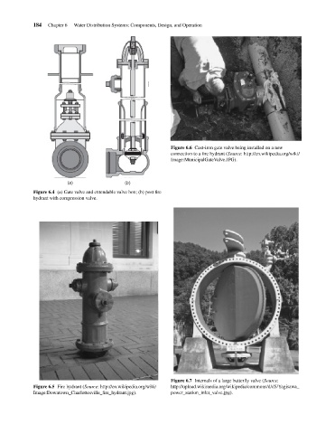
                                                                                       Figure 6.6 Cast-iron gate valve being installed on a new
                                                                                       connection to a fire hydrant (Source: http://en.wikipedia.org/wiki/
                                                                                       Image:MunicipalGateValve.JPG).


                                                 (a)                  (b)
                                    Figure 6.4 (a) Gate valve and extendable valve box; (b) post fire
                                    hydrant with compression valve.


                                                                                       Figure 6.7 Internals of a large butterfly valve (Source:
                                    Figure 6.5 Fire hydrant (Source: http://en.wikipedia.org/wiki/  http://upload.wikimedia.org/wikipedia/commons/d/d5/Yagisawa_
                                    Image:Downtown_Charlottesville_fire_hydrant.jpg).  power_station_inlet_valve.jpg).
   201   202   203   204   205   206   207   208   209   210   211