Page 210 - Water Engineering Hydraulics, Distribution and Treatment
P. 210

188
                                                   Water Distribution Systems: Components, Design, and Operation
                                          Chapter 6
                                      EXAMPLE 6.1 HYDRANT DISCHARGE
                                      Determine the discharge rate of a hydrant using a smooth well rounded 2.5 in. (63.5 mm) outlet at pressures of 13.2, 9.6, 16.8, and
                                      14.5 psig (91.61, 66.62, 116.59, and 100.63 kPa).
                                      Solution 1 (US Customary System):
                                      For smooth well rounded 2.5 in. outlets, c = 0.9
                                          Refer to Table 6.3:
                                                                                    2
                                                                                     √
                                                                                      p
                                                                             Q = 30cd
                                                                                           √
                                                                                           2
                                                                                             p
                                                                             Q = 30 × 0.9 × 2.5
                                                                                   √
                                                                             Q = 169 p.
                                                                                         √
                                                                    For p = 13.2psig Q = 169 13.2 = 610 gpm.
                                                                                         √
                                                                    For p = 9.6psig  Q = 169 9.6 = 520 gpm.
                                                                                         √
                                                                    For p = 16.8psig Q = 169 16.8 = 690 gpm.
                                                                                         √
                                                                    For p = 14.5psig Q = 169 14.5 = 640 gpm.
                                      Solution 2 (SI System):
                                      For smooth well rounded 63.5 mm outlets, c = 0.9
                                          Refer to Table 6.3:
                                                                           Q = 0.0668cd 2  √ p
                                                                           Q = 0.0668 × 0.9 × 63.5 2 √ p
                                                                                   √
                                                                           Q = 242.42 p.
                                                                      For p = 91.61 kPa  Q = 2,320 L/min.
                                                                      For p = 66.62 kPa  Q = 1,979 L/min.
                                                                      For p = 116.59 kPa  Q = 2,618 L/min.
                                                                      For p = 100.63 kPa  Q = 2,432 L/min.
                                    cutting pipes tributary to a central fire hydrant or group of  supply conduit to the high-value district (Fig. 6.10).
                                    hydrants at the center of a circle.                      Further series may be oriented in some other critical
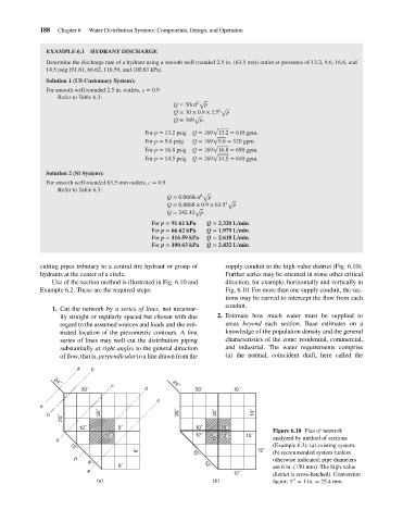
                                        Use of the section method is illustrated in Fig. 6.10 and  direction, for example, horizontally and vertically in
                                    Example 6.2. These are the required steps:               Fig. 6.10. For more than one supply conduit, the sec-
                                                                                             tions may be curved to intercept the flow from each
                                                                                             conduit.
                                        1. Cut the network by a series of lines, not necessar-
                                          ily straight or regularly spaced but chosen with due  2. Estimate how much water must be supplied to
                                          regard to the assumed sources and loads and the esti-  areas beyond each section. Base estimates on a
                                          mated location of the piezometric contours. A first  knowledge of the population density and the general
                                          series of lines may well cut the distribution piping  characteristics of the zone: residential, commercial,
                                          substantially at right angles to the general direction  and industrial. The water requirements comprise
                                          of flow, that is, perpendicular to a line drawn from the  (a) the normal, coincident draft, here called the
                                                a   b
                                         24˝
                                                          c                  24˝
                                                 20˝                d              20˝         10˝
                                                                        e
                                    a
                                      b               20˝                     20˝         20˝        10˝
                                           20˝
                                                12˝         8˝                      10˝    10˝
                                                                                                           Figure 6.10 Plan of network
                                                        12˝                         12˝    12˝     12˝
                                         c                                                16˝              analyzed by method of sections
                                                                                                           (Example 6.2): (a) existing system;
                                             12˝
                                                                  8˝               12˝                12˝  (b) recommended system (unless
                                               d                                                           otherwise indicated, pipe diameters
                                                            8˝                        12˝                  are 6 in. (150 mm). The high-value
                                                   8˝
                                                   e
                                                                                               12˝         district is cross-hatched). Conversion
                                                                                                                 ′′
                                                      (a)                                (b)               factor: 1 = 1in. = 25.4mm.
   205   206   207   208   209   210   211   212   213   214   215