
Page 209 - Water Engineering Hydraulics, Distribution and Treatment
P. 209
187
6.6 Office Studies of Pipe Networks
For outlets of diameter d in. the discharge Q in gpm is
misleading.
2
√
(US customary units)
p
(6.1)
Q = 30cd
where p is the pitot reading in psig and c is the coefficient of
6.6 OFFICE STUDIES OF PIPE NETWORKS
hydrant discharge.
No matter how energetically distribution systems are field-
Equation (6.2) is the hydrant discharge equation using
tested, needed extensions and reinforcements of old networks
the SI units:
and the design of new ones can be adequately identified only
by office studies. Necessary analysis presupposes familiarity
2
√
Q = 0.0668cd
p
(6.2)
(SI units)
with processes of hydraulic computation, including high-
speed computers. Even without computers, however, the best
where p is the pitot reading in kPa, c is the hydrant discharge
processes can be so systematized as to make their application
coefficient, d is the outlet diameter in mm, and Q is the brought into action. Tests of individual hydrants may be quite
hydrant discharge in L/min. a matter of simple arithmetic and pipe-flow tables, diagrams,
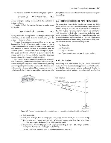
Pressure–discharge relations established in this test are or slide rules. Useful methods of analysis are
illustrated in Fig. 6.9. If the true static pressure is known,
1. Sectioning
a more exact calculation is possible, although the additional
2. Relaxation
labor involved is seldom justified. In accordance with the
common hydraulic analysis of Borda’s mouthpiece, a pres- 3. Pipe equivalence
sure gauge inserted in a hydrant in juxtaposition to the 4. Computer programming and electrical analogy
hydrant outlet to be opened will also record the discharge
pressure otherwise measured by hydrant pitots.
Hydrant tests are sometimes made to ascertain the capac-
6.6.1 Sectioning
ity of individual hydrants and advertise it to firefighters (par-
ticularly to engine companies summoned from neighboring Sectioning is an approximate and, in a sense, exploratory
towns) by painting the bonnet a suitable color. The weakness method, simple in concept and application and widely useful
of this practice is its restriction of flow measurements to sin- provided its limitations are clearly understood. Similar in
gle hydrants. In firefighting, groups of hydrants are normally concept is the circle method, which is usually confined to
Reservoir
Static pressure
A
Normal operating pressure B
Test pressure
C
Engine pressure
D
E
Figure 6.9 Pressure and discharge relations established by hydrant-flow test (see Fig. 6.8 and Table 6.3).
A: Static water table
B: No hydrant discharge. Pressure = 74 psig (514 kPa gauge); pressure drop P due to coincident draft Q
0
C: Hydrant discharge. Pressure = 46 psig (319 kPa gauge); pressure drop P = (74 − 46) = 28 psi
1
(194 kPa) accompanies discharge of Q = 2,980 gpm (908 L/min)
1
D: Engine streams. Pressure 20 psig (140 kPa gauge); pressure drop P = (74 − 20) = 54 psi (375 kPa)
2
accompanies discharge Q = 4,200 gpm (1,280 L/min)
2
E: Hydrant 1, recording residual pressure of hydrant groups shown in Fig. 6.5