
Page 208 - Water Engineering Hydraulics, Distribution and Treatment
P. 208
186
Chapter 6
Water Distribution Systems: Components, Design, and Operation
root of the pressure. Minimum hydrant pressures of 50 psig
(347 kPa) cannot maintain standard fire streams after passing
through as little as 50 ft (15 m) of hose.
gauge
pitot
Motor pumpers commonly deliver up to 1,500 gpm
(5,677 L/min) at adequate pressures. Capacities of
20,000 gpm (75,700 L/min) are in sight, with single streams
discharging as much as 1,000 gpm (3,785 L/min) from 2 in.
(50 mm) nozzles. To furnish domestic and industrial draft and
keep pollution from entering water mains by seepage or fail-
ure under a vacuum, fire engines should not lower pressures
in the mains to less than 20 psig (140 kPa). For large hydrant
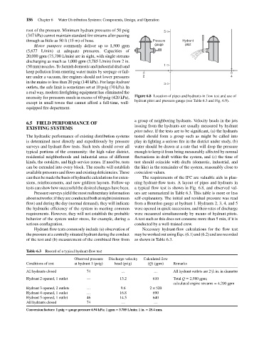
outlets, the safe limit is sometimes set at 10 psig (70 kPa). In 2 Pressure 5 1 3 Hydrant 4
a real way, modern firefighting equipment has eliminated the
necessity for pressures much in excess of 60 psig (420 kPa), Figure 6.8 Location of pipes and hydrants in flow test and use of
hydrant pitot and pressure gauge (see Table 6.3 and Fig. 6.9).
except in small towns that cannot afford a full-time, well-
equipped fire department.
a group of neighboring hydrants. Velocity heads in the jets
6.5 FIELD PERFORMANCE OF
issuing from the hydrants are usually measured by hydrant
EXISTING SYSTEMS
pitot tubes. If the tests are to be significant, (a) the hydrants
The hydraulic performance of existing distribution systems tested should form a group such as might be called into
is determined most directly and expeditiously by pressure play in fighting a serious fire in the district under study, (b)
surveys and hydrant-flow tests. Such tests should cover all water should be drawn at a rate that will drop the pressure
typical portions of the community: the high-value district, enough to keep it from being measurably affected by normal
residential neighborhoods and industrial areas of different fluctuations in draft within the system, and (c) the time of
kinds, the outskirts, and high-service zones. If need be, tests test should coincide with drafts (domestic, industrial, and
can be extended into every block. The results will establish the like) in the remainder of the system, reasonably close to
available pressures and flows and existing deficiencies. These coincident values.
can then be made the basis of hydraulic calculations for exten- The requirements of the IFC are valuable aids in plan-
sions, reinforcements, and new gridiron layouts. Follow-up ning hydrant-flow tests. A layout of pipes and hydrants in
tests can show how successful the desired changes have been. a typical flow test is shown in Fig. 6.8, and observed val-
Pressure surveys yield the most rudimentary information ues are summarized in Table 6.3. This table is more or less
about networks; if they are conducted both at night (minimum self-explanatory. The initial and residual pressure was read
flow) and during the day (normal demand), they will indicate from a Bourdon gauge at hydrant 1. Hydrants 2, 3, 4, and 5
the hydraulic efficiency of the system in meeting common were opened in quick succession, and their rates of discharge
requirements. However, they will not establish the probable were measured simultaneously by means of hydrant pitots.
behavior of the system under stress, for example, during a A test such as this does not consume more than 5 min, if it is
serious conflagration. conducted by a well-trained crew.
Hydrant-flow tests commonly include (a) observation of Necessary hydrant-flow calculations for the flow test
the pressure at a centrally situated hydrant during the conduct may be worked out using Eqs. (6.1) and (6.2) and are recorded
of the test and (b) measurement of the combined flow from as shown in Table 6.3.
Table 6.3 Record of a typical hydrant-flow test
Observed pressure Discharge velocity Calculated flow
Conditions of test at hydrant 1 (psig) head (psig) (Q) (gpm) Remarks
All hydrants closed 74 … … All hydrant outlets are 2 ∕ 2 in. in diameter
1
Hydrant 2 opened, 1 outlet — 13.2 610 Total Q = 2,980 gpm;
calculated engine streams = 4,200 gpm
Hydrant 3 opened, 2 outlets … 9.6 2 × 520
Hydrant 4 opened, 1 outlet … 16.8 690
Hydrant 5 opened, 1 outlet 46 14.5 640
All hydrants closed 74 … …
Conversion factors: 1 psig = gauge pressure 6.94 kPa; 1 gpm = 3.785 L/min; 1 in. = 25.4 mm.