
Page 207 - Water Engineering Hydraulics, Distribution and Treatment
P. 207
185
6.4 System Pressure
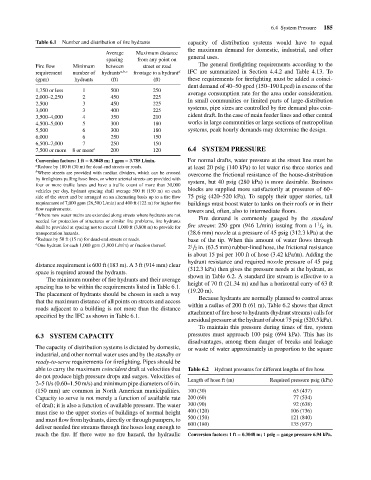
Table 6.1
the maximum demand for domestic, industrial, and other
Maximum distance
Average
general uses.
spacing
from any point on
The general firefighting requirements according to the
between
Fire flow
Minimum
street or road
IFC are summarized in Section 4.4.2 and Table 4.13. To
a,b,c
frontage to a hydrant
requirement
number of
hydrants
these requirements for firefighting must be added a coinci-
(ft)
(ft)
hydrants
(gpm)
dent demand of 40–50 gpcd (150–190 Lpcd) in excess of the
1
500
1,750 or less
average consumption rate for the area under consideration.
2
225
2,000–2,250
450
In small communities or limited parts of large-distribution
225
450
3
2,500
systems, pipe sizes are controlled by fire demand plus coin-
225
3
400
3,000
cident draft. In the case of main feeder lines and other central
210
350
4
3,500–4,000
works in large communities or large sections of metropolitan
5
180
4,500–5,000 Number and distribution of fire hydrants 250 d capacity of distribution systems would have to equal
300
5,500 6 300 180 systems, peak hourly demands may determine the design.
6,000 6 250 150
6,500–7,000 7 250 150
7,500 or more 8 or more e 200 120 6.4 SYSTEM PRESSURE
Conversion factors: 1 ft = 0.3048 m; 1 gpm = 3.785 L/min. For normal drafts, water pressure at the street line must be
a Reduce by 100 ft (30 m) for dead-end streets or roads. at least 20 psig (140 kPa) to let water rise three stories and
b Where streets are provided with median dividers, which can be crossed
overcome the frictional resistance of the house-distribution
by firefighters pulling hose lines, or where arterial streets are provided with
system, but 40 psig (280 kPa) is more desirable. Business
four or more traffic lanes and have a traffic count of more than 30,000
blocks are supplied more satisfactorily at pressures of 60–
vehicles per day, hydrant spacing shall average 500 ft (150 m) on each
side of the street and be arranged on an alternating basis up to a fire flow 75 psig (420–520 kPa). To supply their upper stories, tall
requirement of 7,000 gpm (26,500 L/min) and 400 ft (122 m) for higher fire buildings must boost water to tanks on their roofs or in their
flow requirements. towers and, often, also to intermediate floors.
c
Where new water mains are extended along streets where hydrants are not
Fire demand is commonly gauged by the standard
needed for protection of structures or similar fire problems, fire hydrants 1
shall be provided at spacing not to exceed 1,000 ft (3,800 m) to provide for fire stream: 250 gpm (946 L/min) issuing from a 1 / in.
8
transportation hazards. (28.6 mm) nozzle at a pressure of 45 psig (312.3 kPa) at the
d Reduce by 50 ft (15 m) for dead-end streets or roads. base of the tip. When this amount of water flows through
e One hydrant for each 1,000 gpm (3,800 L/min) or fraction thereof. 1
2 ∕ 2 in. (63.5 mm) rubber-lined hose, the frictional resistance
is about 15 psi per 100 ft of hose (3.42 kPa/m). Adding the
hydrant resistance and required nozzle pressure of 45 psig
distance requirement is 600 ft (183 m). A 3 ft (914 mm) clear
(312.3 kPa) then gives the pressure needs at the hydrant, as
space is required around the hydrants.
shown in Table 6.2. A standard fire stream is effective to a
The minimum number of fire hydrants and their average
height of 70 ft (21.34 m) and has a horizontal carry of 63 ft
spacing has to be within the requirements listed in Table 6.1.
(19.20 m).
The placement of hydrants should be chosen in such a way
Because hydrants are normally planned to control areas
that the maximum distance of all points on streets and access
within a radius of 200 ft (61 m), Table 6.2 shows that direct
roads adjacent to a building is not more than the distance
attachment of fire hose to hydrants (hydrant streams) calls for
specified by the IFC as shown in Table 6.1.
a residual pressure at the hydrant of about 75 psig (520.5 kPa).
To maintain this pressure during times of fire, system
6.3 SYSTEM CAPACITY pressures must approach 100 psig (694 kPa). This has its
disadvantages, among them danger of breaks and leakage
The capacity of distribution systems is dictated by domestic, or waste of water approximately in proportion to the square
industrial, and other normal water uses and by the standby or
ready-to-serve requirements for firefighting. Pipes should be
able to carry the maximum coincident draft at velocities that Table 6.2 Hydrant pressures for different lengths of fire hose
do not produce high pressure drops and surges. Velocities of
Length of hose ft (m) Required pressure psig (kPa)
2–5 ft/s (0.60–1.50 m/s) and minimum pipe diameters of 6 in.
(150 mm) are common in North American municipalities. 100 (30) 63 (437)
Capacity to serve is not merely a function of available rate 200 (60) 77 (534)
of draft; it is also a function of available pressure. The water 300 (90) 92 (638)
must rise to the upper stories of buildings of normal height 400 (120) 106 (736)
and must flow from hydrants, directly or through pumpers, to 500 (150) 121 (840)
600 (180) 135 (937)
deliver needed fire streams through fire hoses long enough to
reach the fire. If there were no fire hazard, the hydraulic Conversion factors: 1 ft = 0.3048 m; 1 psig = gauge pressure 6.94 kPa.