
Page 163 - Wire Bonding in Microelectronics
P. 163
140 Cha pte r F i v e
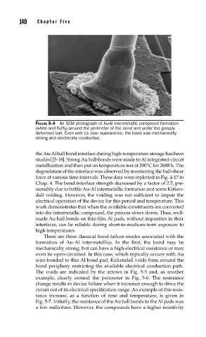
FIGURE 5-4 An SEM photograph of Au-Al intermetallic compound formation
(white and fl uffy) around the perimeter of the bond and under the grossly
deformed ball. Even with its poor appearance, the bond was mechanically
strong and electrically conductive.
the Au-Al ball bond interface during high-temperature storage has been
studied [5-18]. Strong Au ball-bonds were made to Al integrated-circuit
metallization and then put on temperature test at 200°C for 2688 h. The
degradation of the interface was observed by monitoring the ball-shear
force at various time intervals. These data were replotted in Fig. 4-17 in
Chap. 4. The bond interface strength decreased by a factor of 2.5, pre-
sumably due to brittle Au-Al intermetallic formation and some Kirken-
dall voiding. However, the voiding was not sufficient to impair the
electrical operation of the device for this period and temperature. This
work demonstrates that when the available constituents are converted
into the intermetallic compound, the process slows down. Thus, well-
made Au ball-bonds on thin-film Al pads, without impurities in their
interfaces, can be reliable during short-to-medium-term exposure to
high temperatures.
There are three classical bond-failure modes associated with the
formation of Au-Al intermetallics. In the first, the bond may be
mechanically strong, but can have a high-electrical resistance or may
even be open-circuited. In this case, which typically occurs with Au
wire-bonded to thin Al bond pad, Kirkendall voids form around the
bond periphery restricting the available electrical conduction path.
The voids are indicated by the arrows in Fig. 5-5 and, as another
example, clearly around the perimeter in Fig. 5-6. The resistance
change results in device failure when it increases enough to drive the
circuit out of its electrical specification range. An example of this resis-
tance increase, as a function of time and temperature, is given in
Fig. 5-7. Initially, the resistance of the Au ball bonds to the Al pads was
a few milliohms. However, the compounds have a higher resistivity