
Page 132 - 3D Fibre Reinforced Polymer Composites
P. 132
30 Woven Composites 121
paths of centreline of two filler yarn segments. Table 5.4 lists the amplitudes and half
wavelengths of all filler yarn segments as shown in Figure 5.13(b). The tensile stresses
at which failure occurs in all six misaligned filler yarn segments in open mode range
from 483.32 to 533.07 MPa, and those in shear mode range from 437.87 to 462.21 MPa.
These predicted results correlate well with the measured failure strengths in the filler
yarn direction ranging from 445.1 to 509.2 MPa.
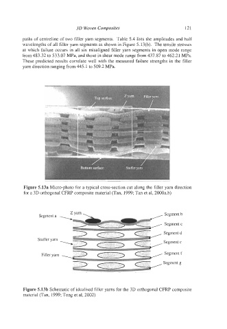
Figure 5.13a Micro-photo for a typical cross-section cut along the filler yarn direction
for a 3D orthogonal CFRP composite material (Tan, 1999; Tan et al, 2000a,b)
Segment a Segment b
Segment c
Segment d
Stuffer yam
. Segment e
Filler yam Segment f
Segment g
Figure 5.13b Schematic of idealised filler yarns for the 3D orthogonal CFRP composite
material (Tan, 1999; Tong et al, 2002)