
Page 186 - A Comprehensive Guide to Solar Energy Systems
P. 186
188 A COmPrehenSIVe GUIDe TO SOlAr enerGy SySTemS
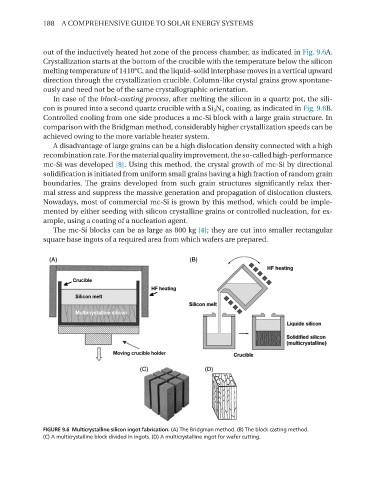
out of the inductively heated hot zone of the process chamber, as indicated in Fig. 9.6A.
Crystallization starts at the bottom of the crucible with the temperature below the silicon
melting temperature of 1410°C, and the liquid–solid interphase moves in a vertical upward
direction through the crystallization crucible. Column-like crystal grains grow spontane-
ously and need not be of the same crystallographic orientation.
In case of the block-casting process, after melting the silicon in a quartz pot, the sili-
con is poured into a second quartz crucible with a Si 3 n 4 coating, as indicated in Fig. 9.6B.
Controlled cooling from one side produces a mc-Si block with a large grain structure. In
comparison with the Bridgman method, considerably higher crystallization speeds can be
achieved owing to the more variable heater system.
A disadvantage of large grains can be a high dislocation density connected with a high
recombination rate. For the material quality improvement, the so-called high-performance
mc-Si was developed [8]. Using this method, the crystal growth of mc-Si by directional
solidification is initiated from uniform small grains having a high fraction of random grain
boundaries. The grains developed from such grain structures significantly relax ther-
mal stress and suppress the massive generation and propagation of dislocation clusters.
nowadays, most of commercial mc-Si is grown by this method, which could be imple-
mented by either seeding with silicon crystalline grains or controlled nucleation, for ex-
ample, using a coating of a nucleation agent.
The mc-Si blocks can be as large as 800 kg [4]; they are cut into smaller rectangular
square base ingots of a required area from which wafers are prepared.
FIGURE 9.6 Multicrystalline silicon ingot fabrication. (A) The Bridgman method. (B) The block casting method.
(C) A multicrystalline block divided in ingots. (D) A multicrystalline ingot for wafer cutting.