
Page 74 - An Introduction to Microelectromechanical Systems Engineering
P. 74
Basic Process Tools 53
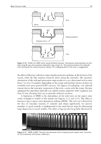
Mask
F
+
SF x
Etch
Silicon
+
nCF x
Deposit polymer
Polymer (nCF )
2
F
+
SF x
Etch
Figure 3.12 Profile of a DRIE trench using the Bosch process. The process cycles between an etch
step using SF gas and a polymer deposition step using C F . The polymer protects the sidewalls
6 4 8
from etching by the reactive fluorine radicals. The scalloping effect of the etch is exaggerated.
the effect of fluorine radicals in removing the protective polymer at the bottom of the
trench, while the film remains relatively intact along the sidewalls. The repetitive
alternation of the etch and passivation steps results in a very directional etch at rates
from 1 to over 15 µm/min, depending on the recipe and machine (newer etchers are
available with more powerful RF sources). The degree of scalloping—the sidewall
texture due to the isotropic component of the etch—varies with the recipe. Recipes
optimized for smoother sidewalls can exhibit surface planarity with roughness less
than 50 nm, allowing their use as optically reflective surfaces.
A limitation of DRIE is the dependence of the etch rates on the aspect ratio
(ratio of height to width) of the trench (see Figures 3.13 and 3.14). The effect is
known as lag or aspect-ratio-dependent etching (ARDE). The etch rate is limited by
the flux of reactants (namely, F radicals) and drops significantly for narrow
trenches. A quick remedy is implemented at the mask layout stage by eliminating
large disparities in trench widths. The effect of lag can also be greatly alleviated by
µ
20 m
Figure 3.13 ARDE in DRIE. The etch rate decreases with increasing trench aspect ratio. (Courtesy
of: GE NovaSensor of Fremont, California.)