
Page 70 - An Introduction to Microelectromechanical Systems Engineering
P. 70
Basic Process Tools 49
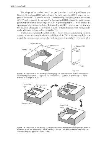
The shape of an etched trench in (110) wafers is radically different (see
Figure 3.7). In silicon (110) wafers, four of the eight equivalent {111} planes are per-
pendicular to the (110) wafer surface. The remaining four {111} planes are slanted
at 35.3º with respect to the surface. The four vertical {111} planes intersect to form a
parallelogram with an inside angle of 70.5º. A groove etched in (110) wafers has the
appearance of a complex polygon delineated by six {111} planes, four vertical and
two slanted. Etching in (110) wafers is useful to form trenches with vertical side-
walls, albeit not orthogonal to each other [9].
While concave corners bounded by {111} planes remain intact during the etch,
convex corners are immediately attacked (Figure 3.8). This is because any slight ero-
sion of the convex corner exposes fast-etching planes (especially {411} planes) other
Slanted {111}
Vertical {111}
Slanted {111}
{110}
Vertical {111}
109.5°
70.5° {111}
Top view
Figure 3.7 Illustration of the anisotropic etching in {110}-oriented silicon. Etched structures are
delineated by four vertical {111} planes and two slanted {111} planes. The vertical {111} planes
intersect at an angle of 70.5º.
Nonetching
Concave corner
layer
{411}
Convex corner
Suspended
beam
Figure 3.8 Illustration of the etching at convex corners and the formation of suspended beams of
++
a material that is not etched (e.g., silicon nitride, p silicon). The {411} planes are frequently the
fastest etching and appear at convex corners.