Page 368 - 02. Subyek Computer Aided Design - Beginner’s Guide to SOLIDWORKS 2019- Level 1 by Alejandro Reyes
P. 368

Detail Drawing


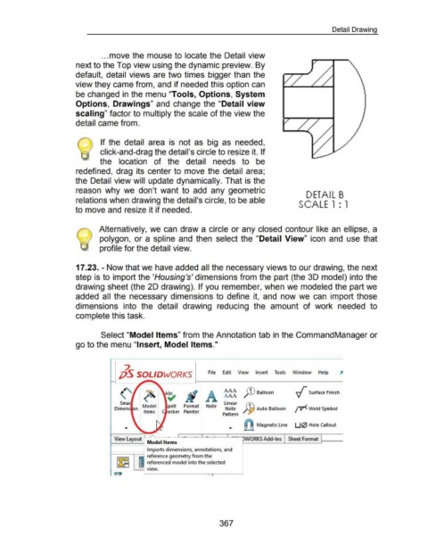
                                                                        ... move the mouse to locate the Detail view


                                                      next to the Top view using the dynamic preview. By


                                                      default, detail views are two times  bigger than  the


                                                      view they came from, and if needed this option can


                                                      be changed in the menu "Tools, Options, System


                                                      Options, Drawings" and  change the "Detail view


                                                      scaling" factor to multiply the scale of the view the


                                                      detail came from.


                                                       @  If the  detail  area  is  not  as  big  as  needed,


                                                                       click-and-drag the detail's circle to resize it. If


                                                                       the  location  of  the  detail  needs  to  be


                                                      redefined, drag  its  center to  move the detail  area;


                                                      the Detail view will  update dynamically. That is the


                                                      reason  why  we  don't  want  to  add  any  geometric
                                                                                                                                                                                                                        DETAIL B
                                                      relations when drawing the detail's circle, to be able
                                                                                                                                                                                                                  SCALE  1 : 1

                                                      to move and resize it if needed.


                                                                      Alternatively, we can  draw a circle or any closed  contour like an ellipse, a


                                                                       polygon, or a  spline  and  then  select the  "Detail  View" icon  and  use that


                                                                       profile for the detail view.


                                                      17 .23. - Now that we have added all the necessary views to our drawing, the next


                                                      step is to import the 'Housing's' dimensions from the part (the 3D model) into the


                                                      drawing sheet (the 2D drawing).  If you remember, when we modeled the part we


                                                      added  all  the  necessary dimensions to  define  it,  and  now we  can  import those


                                                      dimensions  into  the  detail  drawing  reducing  the  amount  of  work  needed  to


                                                      complete this task.


                                                                        Select "Model Items" from the Annotation tab in the CommandManager or


                                                      go to the menu "Insert, Model Items."


                                                                                        ~

                                                                                    j;)S SOLIDWORKS                                                File      Edit       View        Insert        Tools       Window            Help


                                                                                                                                                              AAA
                                                                                                      ~                                                       AAA           }D Balloon                          ~ Surface Finish


                                                                                     Sma                                                                      linear
                                                                                                     Model             pell       Format          Note
                                                                                                                                                               Note  }jj Auto Balloon  JV< Weld Symbol
                                                                                                      Items            ecker  Painter
                                                                                                                                                             Pattern


                                                                                                                                                                             al Magnetic line  U 0  Hole Callout
                                                                                                                                                                            a     o

                                                                                                                              1
                                                                                 View  Layout  Model Items                        - ·     •   L  -     ·        L  -- · ·uwORKS Add-Ins                    Sheet Format


                                                                                                        Imports dimensions, annotations, and

                                                                               --..-----!~ reference geometry from the
                                                                                   1~11                 r:ferenced model into the selected

                                                                                    LJ
                                                                                              ...__  v1ew.
                                                                                 e                                                               I  I   I


                                                                                                                                                           367
   363   364   365   366   367   368   369   370   371   372   373