
Page 684 - 02. Subyek Computer Aided Design - Beginner’s Guide to SOLIDWORKS 2019- Level 1 by Alejandro Reyes
P. 684
Animation and Rendering
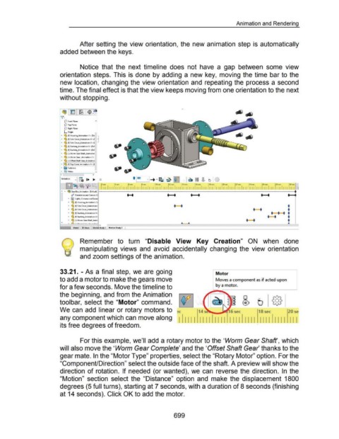
After setting the view orientation, the new animation step is automatically
added between the keys.
Notice that the next timeline does not have a gap between some view
orientation steps. This is done by adding a new key, moving the time bar to the
new location, changing the view orientation and repeating the process a second
time. The final effect is that the view keeps moving from one orientation to the next
without stopping.
C!J Front Plane
dJ Top Plane
dJ Right Plane
L Origin
., ~ (f) Housing_Animation< 1> (De-
• <SJ (f) SideCovor_Animation<1> (I e
• <SJ (f) Side Covor_Animation<2> (I
• <SJ (f) Bushing_Animation< 1> (Del
• <SJ (f) Bushing_Animation<2> (Del
• <SJ (-) Worm Gear Shaft..Animatior
• <SJ (-)Worm Gtar _Animation< I>
• <SJ (-)Offset Shaft Gear_Animation
• lot§ (f) TopCover_Animation<l> ([
• [l FasteneJs
• @gl Mates ..,
< >
Animation .., I g. 1.... ....
LSZJ~ ~ '\P
"' • ~ GearBox_Animation (Oefoult) ll---------7----------:-----:-------~----:------------:------:-----.
• • • • • •
d Orientation and Camera Vi
• fi) Lights .. Cameras and Scene
• ~ (f) Housing_Animation<l>
•
• ~ (f) Side Cover_Animation< • • tn--r,. •
•••
• ~ (f) Side Cover _Animation<
• ~ (f) Bushing,.Animation<1> .-. .
• <SJ (f) Bushing_Animotion<2>
• <SJ (-) Worm GeorShaft_Anim ~'· .
--~---------·-·----~----~--~----~---·
v " l'l"'\. ' ' 1u.__. r ••• ..... : ...... : ...
Remember to turn "Disable View Key Creation" ON when done
manipulating views and avoid accidentally changing the view orientation
and zoom settings of the animation.
33.21. - As a final step, we are going Motor
to add a motor to make the gears move Moves a component as if acted upon
for a few seconds. Move the timeline to by a motor. ______ _,
the beginning, and from the Animation 1\f/
toolbar, select the "Motor" command. v S tJ {§}
We can add linear or rotary motors to c 1s sec 20 se-
any component which can move along I Ill I II II II II I Ill II II II II Ill I II I
its free degrees of freedom. I • I I
For this example, we'll add a rotary motor to the 'Worm Gear Shaft', which
will also move the 'Worm Gear Complete' and the 'Offset Shaft Gear thanks to the
gear mate. In the "Motor Type" properties, select the "Rotary Motor" option. For the
"ComponenUDirection" select the outside face of the shaft. A preview will show the
direction of rotation. If needed (or wanted), we can reverse the direction. In the
"Motion" section select the "Distance" option and make the displacement 1800
degrees (5 full turns), starting at 7 seconds, with a duration of 8 seconds (finishing
at 14 seconds). Click OK to add the motor.
699