
Page 511 - Biaxial Multiaxial Fatigue and Fracture
P. 511
Geometry Variation and Life Estimates of Biaxial Fatigue Specimens 495
direction and then deviates to the 8= 45' direction as it continues to propagate. Furthermore,
for the specimens subjected to the lowest load levels of 12.5kN and lOkN (Specimens D and
E), the crack initiates and propagates in the 8= 0" direction only. This pattern of crack
direction is in good agreement with the subsurface strain model predictions as is shown in Fig.
6. The predicted lives for Specimens D and E in the 8= 0' direction are shorter than those
predicted in the 8= 45' direction.
Crack Initiation
To ensure that cracks initiate and propagate at the center of the specimens, three types of stress
raiser geometries were considered: slot, spherical, and drill notches. The local refined FEA
mesh for the three notch types is shown in Fig. 9. As mentioned earlier the slot was made by
Electro-Discharge Machining (EDM). The spherical notch was machined by using a ball nose
cutter tool and indenting the tool to a depth of 1 mm. A through hole was machined by using a
lmm fine drili tool. These notch types were tried during the optimization of the anticlastic
bending specimen geometry in order to investigate the stress and strain distribution near the
crack. The FEA simulation indicated that, for the symmetry of the biaxial stresses, the sphere
was the most suitable notch type.
0.014 r . I I
0
, --A-- l=l.Omm --0--x=o.5mm
.-- -.
-
-
-
0*)02 L T--- I--- I---
2 3 4 5 6 7
Log (Life)
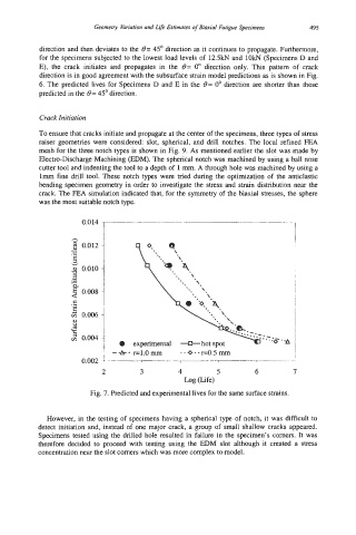
Fig. 7. Predicted and experimental lives for the same surface strains.
However, in the testing of specimens having a spherical type of notch, it was difficult to
detect initiation and, instead of one major crack, a group of small shallow cracks appeared.
Specimens tested using the drilled hole resulted in failure in the specimen's comers. It was
therefore decided to proceed with testing using the EDM slot although it created a stress
concentration near the slot comers which was more complex to model.