
Page 188 - Biomedical Engineering and Design Handbook Volume 1, Fundamentals
P. 188
BIOMECHANICS OF THE MUSCULOSKELETAL SYSTEM 165
A
Straight
–5
Muscle moment arm (mm) –15 Fixed
–10
–20
–25 Obstacle
0° Rotation
45° Rotation
–30
0 20 40 60 80 100 120 140 160
Elbow flexion (deg)
B
–22 Obstacle
Muscle moment arm (mm) –24 Fixed
–26
0° Rotation
45° Rotation
–28
40 45 50 55 60 65 70
Elbow flexion (deg)
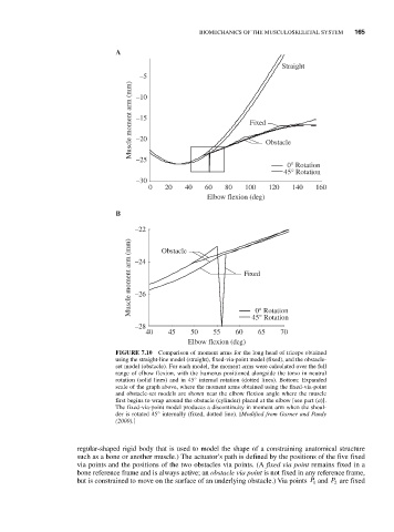
FIGURE 7.10 Comparison of moment arms for the long head of triceps obtained
using the straight-line model (straight), fixed-via-point model (fixed), and the obstacle-
set model (obstacle). For each model, the moment arms were calculated over the full
range of elbow flexion, with the humerus positioned alongside the torso in neutral
rotation (solid lines) and in 45° internal rotation (dotted lines). Bottom: Expanded
scale of the graph above, where the moment arms obtained using the fixed-via-point
and obstacle-set models are shown near the elbow flexion angle where the muscle
first begins to wrap around the obstacle (cylinder) placed at the elbow [see part (a)].
The fixed-via-point model produces a discontinuity in moment arm when the shoul-
der is rotated 45° internally (fixed, dotted line). [Modified from Garner and Pandy
(2000).]
regular-shaped rigid body that is used to model the shape of a constraining anatomical structure
such as a bone or another muscle.) The actuator’s path is defined by the positions of the five fixed
via points and the positions of the two obstacles via points. (A fixed via point remains fixed in a
bone reference frame and is always active; an obstacle via point is not fixed in any reference frame,
but is constrained to move on the surface of an underlying obstacle.) Via points P 1 and P 2 are fixed