
Page 190 - Biomedical Engineering and Design Handbook Volume 1, Fundamentals
P. 190
BIOMECHANICS OF THE MUSCULOSKELETAL SYSTEM 167
to bone A, while SS, 2 , and S 3 are fixed to bone B. For a given configuration of the joint, the path
1
of all segments of the muscle are known, except those between the bounding fixed via points, P 2 and
S 3 . The path of the actuator is known once the positions of the obstacle via points Q and T have
been found.
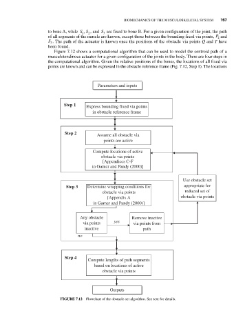
Figure 7.12 shows a computational algorithm that can be used to model the centroid path of a
musculotendinous actuator for a given configuration of the joints in the body. There are four steps in
the computational algorithm. Given the relative positions of the bones, the locations of all fixed via
points are known and can be expressed in the obstacle reference frame (Fig. 7.12, Step 1). The locations
Parameters and inputs
Step 1 Express bounding fixed via points
in obstacle reference frame
Step 2
Assume all obstacle via
points are active
Compute locations of active
obstacle via points
[Appendices C-F
in Garner and Pandy (2000)]
Use obstacle set
Step 3 Determine wrapping conditions for appropriate for
obstacle via points reduced set of
[Appendix A obstacle via points
in Garner and Pandy (2000)]
Any obstacle Remove inactive
via points yes via points from
inactive path
no
Step 4
Compute lengths of path segments
based on locations of active
obstacle via points
Outputs
FIGURE 7.12 Flowchart of the obstacle-set algorithm. See text for details.