
Page 191 - Biomedical Engineering and Design Handbook Volume 1, Fundamentals
P. 191
168 BIOMECHANICS OF THE HUMAN BODY
of the remaining via points in the actuator’s path, the obstacle via points, can be calculated using one
or more of the four different obstacle sets given in Apps. C through F in Garner and Pandy (2000)
(Fig. 7.12, Step 2). Once the locations of the obstacle via points are known, a check is made to deter-
mine whether any of these points should be inactive (Fig. 7.12, Step 3). If an obstacle via point
should be inactive, it is removed from the actuator’s path and the locations of the remaining obstacle
via points are then recomputed (Fig. 7.12, repeat Steps 2 and 3). Finally, the lengths of the segments
between all of the active via points along the actuator’s path are computed (Fig. 7.12, Step 4).
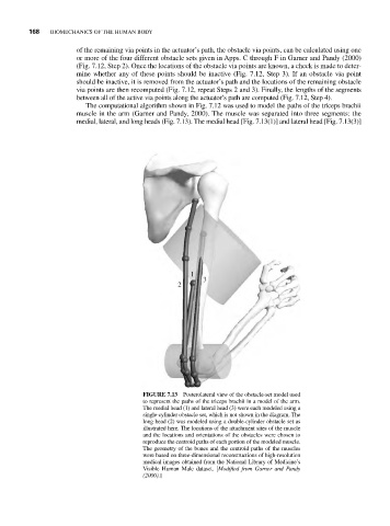
The computational algorithm shown in Fig. 7.12 was used to model the paths of the triceps brachii
muscle in the arm (Garner and Pandy, 2000). The muscle was separated into three segments: the
medial, lateral, and long heads (Fig. 7.13). The medial head [Fig. 7.13(1)] and lateral head [Fig. 7.13(3)]
1
3
2
FIGURE 7.13 Posterolateral view of the obstacle-set model used
to represent the paths of the triceps brachii in a model of the arm.
The medial head (1) and lateral head (3) were each modeled using a
single-cylinder obstacle set, which is not shown in the diagram. The
long head (2) was modeled using a double-cylinder obstacle set as
illustrated here. The locations of the attachment sites of the muscle
and the locations and orientations of the obstacles were chosen to
reproduce the centroid paths of each portion of the modeled muscle.
The geometry of the bones and the centroid paths of the muscles
were based on three-dimensional reconstructions of high-resolution
medical images obtained from the National Library of Medicine’s
Visible Human Male dataset. [Modified from Garner and Pandy
(2000).]