
Page 189 - Biomedical Engineering and Design Handbook Volume 1, Fundamentals
P. 189
166 BIOMECHANICS OF THE HUMAN BODY
A
Bone A
Y A
X A
Joint Bone B
X B P 1
Y B
Muscle
Centroid line
P 1 P 2
Y C
X C
S 3
P 2 S 2
Y C
Q
X C
S 1 S
T S 3 S 2 1
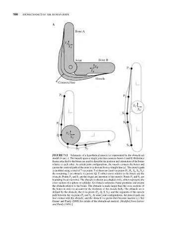
FIGURE 7.11 Schematic of a hypothetical muscle (a) represented by the obstacle-set
model (b and c). The muscle spans a single joint that connects bones A and B. Reference
frames attached to the bones are used to describe the position and orientation of the bones
relative to each other. At certain joint configurations, the muscle contacts the bones and
causes the centroid path of the muscle to deviate from a straight line (a). The muscle path
is modeled using a total of 7 via points: 5 of these are fixed via points (P , P , S , S , S );
2
1
1
2
3
the remaining 2 are obstacle via points (Q, T) which move relative to the bones and the
obstacle. Points P and S are the origin and insertion of the muscle. Points P and S are
2
3
1
1
bounding-fixed via points. The obstacle is shown as a shaded circle, which represents the
cross section of a sphere or cylinder. An obstacle reference frame positions and orients
the obstacle relative to the bones. The obstacle is made larger than the cross sections of
the bones in order to account for the thickness of the muscle belly. The obstacle set is
defined by the obstacle, the 4 via points (P , Q, T, S ), and the segments of the muscle
2
3
path between the via points P and S . At some joint configurations, the muscle path can
2
3
lose contact with the obstacle, and the obstacle via points then become inactive (c). See
Garner and Pandy (2000) for details of the obstacle-set method. [Modified from Garner
and Pandy (2000).]