
Page 192 - Biomedical Engineering and Design Handbook Volume 1, Fundamentals
P. 192
BIOMECHANICS OF THE MUSCULOSKELETAL SYSTEM 169
were each modeled using a single-cylinder obstacle set (not shown in Fig. 7.13). The long head
[Fig. 7.13(2)] was modeled using a double-cylinder obstacle set as illustrated. The locations of the
attachment sites of each muscle segment and the loca-
tions and orientations of the obstacles were chosen to
reproduce the centroid paths of each head as accu- B
rately as possible. The geometry of the bones and the
centroid paths of the muscle segments were obtained
from three-dimensional reconstructions of high-resolution S
medical images obtained from the National Library
of Medicine’s Visible Human Male dataset (Garner
and Pandy, 2001). Because the path of a muscle is not
improperly constrained by contact with neighboring
muscles and bones, the obstacle-set method produces not
only accurate estimates of muscle moment arms, but also
smooth moment arm-joint angle curves, as illustrated in
Fig. 7.10.
7.4.3 Muscle Moment Arms
R
Muscles develop forces and cause rotation of the bones O A B
ω
about a joint. The tendency of a musculotendinous Q OQ •
actuator to rotate a bone about a joint is described by r
the actuator’s moment arm. Two methods are commonly
used to measure the moment arm of an actuator—the P
geometric method and the tendon excursion method.
In the geometric method, a finite center of rotation is N
found using x-rays, computed tomography, or magnetic
resonance imaging, and the moment arm is found by
measuring the perpendicular distance from the joint
center to the line of action of the muscle (Jensen and A
Davy, 1975). In the tendon excursion method, the change
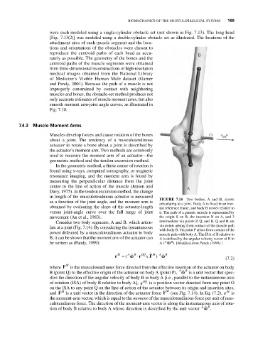
in length of the musculotendinous actuator is measured FIGURE 7.14 Two bodies, A and B, shown
as a function of the joint angle, and the moment arm is articulating at a joint. Body A is fixed in an iner-
obtained by evaluating the slope of the actuator-length tial reference frame, and body B moves relative to
versus joint-angle curve over the full range of joint it. The path of a generic muscle is represented by
movement (An et al., 1983). the origin S on B, the insertion N on A, and 3
Consider two body segments, A and B, which articu- intermediate via points P, Q, and R. Q and R are
late at a joint (Fig. 7.14). By considering the instantaneous via points arising from contact of the muscle path
with body B. Via point P arises from contact of the
power delivered by a musculotendinous actuator to body muscle path with body A. The ISA of B relative to
B, it can be shown that the moment arm of the actuator can A is defined by the angular velocity vector of B in
A
be written as (Pandy, 1999): A ( v B ). [Modified from Pandy (1999).]
A
M
A
ˆ
x
r M = ( ˆ v B • r OQ ˆ F ) v B
(7.2)
where F M is the musculotendinous force directed from the effective insertion of the actuator on body
B (point Q) to the effective origin of the actuator on body A (point P), ˆ v B is a unit vector that spec-
A
ifies the direction of the angular velocity of body B in body A [i.e., parallel to the instantaneous axis
of rotation (ISA) of body B relative to body A], r OQ is a position vector directed from any point O
on the ISA to any point Q on the line of action of the actuator between its origin and insertion sites,
ˆ M
and F is a unit vector in the direction of the actuator force F M (see Fig. 7.14). In Eq. (7.2), r M is
the moment-arm vector, which is equal to the moment of the musculotendinous force per unit of mus-
culotendinous force. The direction of the moment-arm vector is along the instantaneous axis of rota-
tion of body B relative to body A whose direction is described by the unit vector ˆ .v B
A