
Page 393 - Boiler_Operators_Handbook,_Second_Edition
P. 393
378 Boiler Operator’s Handbook
“bumpless” applied to controllers. On the off chance manual signal and you got to adjust it until it matched
that you will get to work in an antique boiler plant I the automatic output before turning the knob another
think it’s a good idea for you to get an understanding of 1/4 turn to manual. When transferring from manual to
why those features were added so you can deal with the auto it showed the automatic output so you could bias
situation. it to match the manual output before switching to auto.
Early pneumatic control systems that included (I’ll get to explaining bias in a bit) As you can see, you
hardware like the ratio totalizer had separate manual/ had to perform a signal matching procedure during the
auto stations which were flush mounted on the panel transfer from hand to auto and vice versa or you got a
and gave people the option of controlling the process by bump.
hand. When it was considered necessary to give people Those old stations worked pretty well as long as
the option of changing the setpoint the station also in- they didn’t leak much and you were quick at adjust-
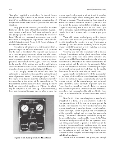
cluded that adjustment. Figure 11-11 shows what one of ing the signal for the transfer. In a way I was sorry to
those stations looked like. see them go because I could adjust my manual outputs
The setpoint adjustment was nothing more than a where I wanted the controls to be if I switched to manual
pressure regulator with the adjustment knob penetrat- and I knew they would go there.
ing the front of the station. The setpoint was indicated You may also run into controllers with a balance
on a pressure gauge mounted above the adjustment indicator. It consists of a clear plastic tube that’s visible
knob. The output of the controller was indicated on through a slot in the front plate of the controller and
another pressure gauge and another pressure regulator contains a small ball that fits inside the tube with very
produced the manual output signal. The valve handle little clearance. One side of the tube is connected to the
in the middle of the station was used to switch from manual output and the other to the automatic. When
automatic to manual and back to automatic; however, it you’re ready to switch from one to the other you adjust
wasn’t as simple as just turning that pointed knob. the manual output until the ball floats to the middle
If you simply twisted the valve knob from the then throw the auto/manual selector switch over.
automatic to manual position and the automatic and As pneumatic controls improved the manufactur-
manual pressures weren’t the same you got a “bump;” ers included additional little controllers inside their de-
the output would jump from the output produced by vices so the automatic signal automatically followed the
the controller to the setting of the manual station. To manual output and the manual output was automati-
transfer from auto to manual without a bump the valve cally adjusted to match automatic to permit rapid and
knob had intermediate positions at 1/4 turn for adjust- “procedureless-bumpless” transfer between manual
ing the outputs to match them up. When transferring and automatic operation. Electronic controls had similar
from auto to manual the gage was switched to show the procedures that were replaced by add-ins. Similar func-
tions are understood to be included in modern control-
lers.
Now for bias, it’s a control engineer’s term for add
or subtract. It is done a lot in controllers but most of the
time you don’t see it. It became an integral part of the
manual/auto stations so you could line up auto and
manual signals and it was done in one control regulator
where the output of the regulator was a combination
of the controller output and pressure that opposed a
spring. The manual adjustment loaded the spring and
the assembly looked something like Figure 11-12. When
the control designers noticed that we operators used
that spring adjustment to produce a difference in the
output of two manual/auto stations using the same
control signal (like on coal pulverizers where we could
bias the primary air and coal feed) they simply manu-
factured another faceplate with that regulator on it and
called it a bias station.
Figure 11-11. Early pneumatic H/A station As far as I’m concerned I’ve given you enough