
Page 398 - Boiler_Operators_Handbook,_Second_Edition
P. 398
Controls 383
to produce the pressure in the bellows. holds the valve in position. These valves have a droop
Any of these systems rely on minimal changes in but it is so small that you don’t notice it. They require
temperature at the capillary and bellows which inter- a minimum difference in inlet and outlet pressures and
feres with control based on the temperature at the probe. actually work a little better as the pressure difference in-
The capillaries are also very narrow to minimize the creases because the main valve operation is determined
amount of fluid they contain and the effect of heating or by the difference between inlet and outlet pressure.
cooling them. Those small capillaries are easily pinched A self contained main flow control valve can be
to block the transmission of pressure from the probe to piloted by a small float valve, temperature element, or
the bellows or nicked, cracked, or cut to drain the fluid other devices to achieve control by using the difference
and eliminate control. between inlet and outlet pressure of the controlled fluid.
Simple diaphragm operated valves and internal Some important considerations for this control are fil-
lever actuated valves have their limits when it comes to tering or installation of a strainer on the small stream
handling large pressure drops, large flow rates, or when of fluid used for control so it doesn’t plug up the pilot
low droop is desired. Pilot operated self contained con- valve or the orifice that bleeds the fluid downstream.
trol valves do a great job of handling those conditions. The flow for the pilot is so low that many piloted
A pilot operated valve is basically a duplex valve where gas pressure regulators do not have a vent line. There’s
the pilot controls the pressure by controlling the main a small orifice in the spring chamber that can bleed
valve. off enough gas to allow the valve to work when the
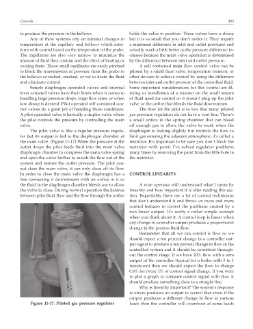
The pilot valve is like a regular pressure regula- diaphragm is leaking slightly but restricts the flow to
tor but its output is fed to the diaphragm chamber of limit gas entering the adjacent atmosphere; it’s called a
the main valve. (Figure 11-17) When the pressure at the restrictor. It’s important to be sure you don’t block the
outlet drops the pilot feeds fluid into the main valve restrictor with paint; I’ve solved regulator problems
diaphragm chamber to compress the main valve spring many times by removing the paint from the little hole in
and open the valve further to match the flow out of the the restrictor.
system and restore the outlet pressure. The pilot can-
not close the main valve, it can only close off its flow.
In order to close the main valve the diaphragm has a CONTROL LINEARITY
line connecting it downstream with an orifice in it so
the fluid in the diaphragm chamber bleeds out to allow A wise operator will understand what I mean by
the valve to close. During normal operation the balance linearity and how important it is after reading this sec-
between pilot fluid flow and the flow through the orifice tion. Regrettably there are a lot of control technicians
that don’t understand it and throw on more and more
control features to correct the problems created by a
non-linear output. It’s really a rather simple concept
when you think about it. A control loop is linear when
any change in controller output produces a proportional
change in the process fluid flow.
Remember that all we can control is flow so we
should expect a ten percent change in a controller out-
put signal to produce a ten percent change in flow in the
controlled system and it should be consistent through-
out the control range. If we have 20% flow with a zero
output of the controller (typical for a boiler with 5 to 1
turndown) then we should expect the flow to change
0.8% for every 1% of control signal change. If you were
to plot a graph to compare control signal with flow it
should produce something close to a straight line.
Why is linearity important? The system’s response
to errors produces an output to correct that error; if the
output produces a different change in flow at various
Figure 11-17. Piloted gas pressure regulator loads then the controller will overshoot at some loads