
Page 396 - Boiler_Operators_Handbook,_Second_Edition
P. 396
Controls 381
symbol indicates it’s panel mounted so the controller thermostat to monitor the gas pilot for burner safety. A
is mounted in a control panel. Sometimes double lines bulb placed in the furnace over the pilot fire contains a
near the top and bottom of the drawing distinguish a liquid which evaporates to generate an internal pressure
separation between panel and field. The two figures conducted through a length of very small tubing to com-
could be modified to eliminate the lines representing press a spring opposite a bellows in the valve body. As
logic flow by clustering symbols together. The control- long as the pilot burns the bellows holds a latch which
ler in Figure 11-14 could be shown alongside the valve holds up a disc in the valve body to admit gas to the
positioner which would indicate that all those functions pilot. When you light one of these you hold in a button
were in a controller and positioner mounted in one that opens the valve to admit gas to the pilot. Once the
enclosure on the control valve. The PID controller and heat of the pilot generates enough pressure in the ther-
transmitter symbols could be put together to indicate mostat assembly it holds the pilot valve open and you
the controller and transmitter are in one package. can release the button.
Now that we’ve covered control concepts and con- When you release the button it allows a valve to
trol diagrams let’s look at some control systems used in open that admits pilot gas pressure to the main valve
boiler plants. control. The temperature of the water in the heater is
sensed by a bulb inserted into the side of the heater.
That bulb can contain another liquid that expands to
compress a spring or linkage that uses the difference
in thermal expansion of metals for a mechanical move-
ment relative to the temperature of the water in the
tank. When you adjust the temperature knob on the side
of the control valve you change the relative position of
the linkage or spring and another small valve to select
the desired starting temperature. When the water cools
a switching valve opens to admit pilot gas pressure to
a diaphragm which opens the main valve. The main
valve admits gas that is ignited by the pilot and heats
the water. During that operation the main valve also
functions as a pressure regulator to maintain a constant
gas pressure to the burner. When the temperature rises a
set amount above the starting temperature the switching
valve closes the pilot gas supply to the main valve dia-
phragm and drains the gas over the diaphragm to shut
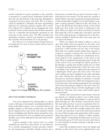
Figure 11-15. Single loop diagram, ISA symbols off the fire. The main valve closes until another operat-
ing cycle starts.
Modern self contained hot water heater valves do
SELF CONTAINED CONTROLS not operate on continuous pilot to save a little energy.
They also eliminate the old problem we always had of
You can be impressed by photographs of control pilots blowing out. They include a piezoelectric starter
rooms with long curved panels containing hundreds of that uses pilot gas flow to power a generator that cre-
knobs and buttons under a row of monitors that reveal ates a spark to light the pilot as the water temperature
graphic displays of the boiler systems but you should drops. The main valves have double seated valve discs
also be impressed by some of the self contained control to ensure safe operation. Look at the instruction manual
devices including some that have been around for years for one of them to gain some appreciation of how some-
and proven themselves to be so reliable and economical thing that appears to be so simple is rather sophisti-
that they may not be replaced by the end of the twenty- cated. I think I would prefer the older type, however. If
first century. the electricity goes off I still want my hot water heater
A good example is the control valve on a little to work. Despite all modern miracles I still get a lot of
residential gas fired hot water heater. In one little box power outages.
it is a burner management system, pressure control- Some self contained control valves are simple and
ler and temperature controller. Simple versions use a effective so they don’t have to be sophisticated. A gas