
Page 391 - Boiler_Operators_Handbook,_Second_Edition
P. 391
376 Boiler Operator’s Handbook
upset the performance of our controller.
There’s also the problems associated with the con-
trolled fluid as well. When the valve is closed the differ-
ence in valve inlet and outlet pressures act on the area of
the valve opening, adding another force to the valve stem.
If the valve is a boiler control valve it can work perfectly
fine when the boiler is operating but leak when the boiler
is shut down because the pressure drop across the valve
disc is so great that it overcomes the forces produced by
control pressure. All these factors can be overcome by
making sure the combination of diaphragm area and
valve chamber pressure will keep the valve shut. Adding
a positioner also helps because it can operate with higher
actuator pressures using a separate air supply and match
Figure 11-8. Simple pneumatic control valve diagram the valve position to the control signal.
A valve positioner is just another controller. It
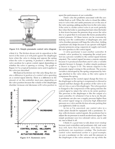
where it is. The friction always acts in opposition to the
controls valve position by comparing the actual posi-
travel of the stem so it will push against the diaphragm
tion (as a process variable) to the control signal (remote
force when the valve is closing and oppose the spring
setpoint). The control signal becomes a remote setpoint
when the valve is opening. It produces a difference in
because it is produced elsewhere and it’s also a variable
valve position for a given control signal depending on
setpoint because it changes. A rather simple positioner
whether the valve is opening or closing. The graph in
is shown in Figure 11-10. The remote setpoint is the
Figure 11-9 is a typical hysteresis curve and it applies to
pneumatic signal coming to the positioner. The process
the valve just described.
variable is developed by the spring compressed by link-
Mechanical hysteresis isn’t the only thing that cre-
age attached to the valve stem; as the valve opens it
ates a difference in position of a control valve operating
compresses the spring.
on a control signal directly. There is a difference in the
Changes in the control signal change the force on
amount of air the controller must pass depending on
the diaphragm so the spring is compressed or allowed to
the valve position because the volume of the diaphragm
expand and that changes the position of the valve to di-
chamber increases and decreases with valve position to
vert air into or out of the diaphragm. The valve position
is changed so the compression of the spring matches the
control signal to return the valve to its center position.
The pressure in the diaphragm is like the output of a
reset controller, it’s whatever it has to be to do the job.
A positioner can also use a supply pressure higher than
the control signal range to overcome high differential
pressure on a valve and the friction of some packing that
you tightened a little too much.
As far as I’m concerned, any control valve in a
boiler plant should be equipped with a positioner. To-
day, with electronic control signals, the positioner has to
adjust the air pressure to match an electronic signal. One
simple positioner uses two solenoid valves, one to add
air, one to bleed it off.
I think it’s a good time to talk about reset windup
because reset controllers and positioners did, and some
may still, have that characteristic. Also these valve
positioners can experience windup. The feedwater
control valve mentioned earlier is a good example;
we put a positioner on the valve and the pressure in
Figure 11-9. Hysteresis curve the diaphragm of the valve actuator ran up while the