
Page 399 - Boiler_Operators_Handbook,_Second_Edition
P. 399
384 Boiler Operator’s Handbook
and lag at others. Remember the joking comment “It al- an excellent linear relationship between control signal
ways works fine when the serviceman is here?” The pri- (controller output) and flow.
mary reason why that is true so often is the serviceman One problem I’ve noticed with microprocessor
is always there when the loads are the same as they were based controllers is technicians tend to avoid the rather
when he tuned the controller. If you run into that situ- laborious process of cutting a cam on a positioner by
ation you should insist the serviceman show up when simply programming a function generator in the con-
the system is acting up; you can predict your loads and troller. That function generator produces an output
you should be able to relate load and control problems. that is a function of the controller output so the result
If, however, the technician tunes the system for those is linear control. It works fine when the controls are in
loads it probably won’t work well at the loads where she automatic but it ain’t worth a damn when you’re trying
originally tuned it. If the system is linear those problems to operate a boiler on hand.
won’t occur. I insist that the linearity be established at the final
To understand why linearity is difficult to achieve drive (damper actuator, fuel control valve, etc.) so the re-
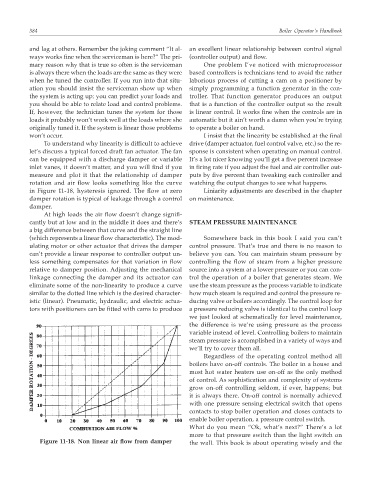
let’s discuss a typical forced draft fan actuator. The fan sponse is consistent when operating on manual control.
can be equipped with a discharge damper or variable It’s a lot nicer knowing you’ll get a five percent increase
inlet vanes, it doesn’t matter, and you will find if you in firing rate if you adjust the fuel and air controller out-
measure and plot it that the relationship of damper puts by five percent than tweaking each controller and
rotation and air flow looks something like the curve watching the output changes to see what happens.
in Figure 11-18, hysteresis ignored. The flow at zero Liniarity adjustments are described in the chapter
damper rotation is typical of leakage through a control on maintenance.
damper.
At high loads the air flow doesn’t change signifi-
cantly but at low and in the middle it does and there’s STEAM PRESSURE MAINTENANCE
a big difference between that curve and the straight line
(which represents a linear flow characteristic). The mod- Somewhere back in this book I said you can’t
ulating motor or other actuator that drives the damper control pressure. That’s true and there is no reason to
can’t provide a linear response to controller output un- believe you can. You can maintain steam pressure by
less something compensates for that variation in flow controlling the flow of steam from a higher pressure
relative to damper position. Adjusting the mechanical source into a system at a lower pressure or you can con-
linkage connecting the damper and its actuator can trol the operation of a boiler that generates steam. We
eliminate some of the non-linearity to produce a curve use the steam pressure as the process variable to indicate
similar to the dotted line which is the desired character- how much steam is required and control the pressure re-
istic (linear). Pneumatic, hydraulic, and electric actua- ducing valve or boilers accordingly. The control loop for
tors with positioners can be fitted with cams to produce a pressure reducing valve is identical to the control loop
we just looked at schematically for level maintenance,
the difference is we’re using pressure as the process
variable instead of level. Controlling boilers to maintain
steam pressure is accomplished in a variety of ways and
we’ll try to cover them all.
Regardless of the operating control method all
boilers have on-off controls. The boiler in a house and
most hot water heaters use on-off as the only method
of control. As sophistication and complexity of systems
grow on-off controlling seldom, if ever, happens; but
it is always there. On-off control is normally achieved
with one pressure sensing electrical switch that opens
contacts to stop boiler operation and closes contacts to
enable boiler operation, a pressure control switch.
What do you mean “Ok, what’s next?” There’s a lot
more to that pressure switch than the light switch on
Figure 11-18. Non linear air flow from damper the wall. This book is about operating wisely and the