
Page 277 - Boiler plant and distribution system optimization manual
P. 277
262 Boiler Plant and Distribution System Optimization Manual
Float and thermostatic (F&T) traps are a
modification of the float trap in that the thermo-
static air vent is an integral part of the trap (Fig-
ure 14.12).
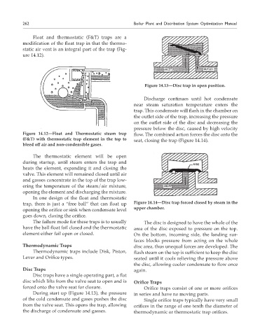
Figure 14.13—Disc trap in open position.
Discharge continues until hot condensate
near steam saturation temperature enters the
trap. This condensate will flash in the chamber on
the outlet side of the trap, increasing the pressure
on the outlet side of the disc and decreasing the
pressure below the disc, caused by high velocity
Figure 14.12—Float and Thermostatic steam trap flow. The combined action forces the disc onto the
(F&T) with thermostatic trap element in the top to seat, closing the trap (Figure 14.14).
bleed off air and non-condensible gases.
The thermostatic element will be open
during startup, until steam enters the trap and
heats the element, expanding it and closing the
valve. This element will remained closed until air
and gasses concentrate in the top of the trap low-
ering the temperature of the steam/air mixture,
opening the element and discharging the mixture.
In one design of the float and thermostatic
trap, there is just a “free ball” that can float up Figure 14.14—Disc trap forced closed by steam in the
upper chamber.
opening the orifice or sink when condensate level
goes down, closing the orifice.
The failure mode for these traps is to usually The disc is designed to have the whole of the
have the ball float fail closed and the thermostatic area of the disc exposed to pressure on the top.
element either fail open or closed. On the bottom, incoming side, the landing sur-
faces blocks pressure from acting on the whole
Thermodynamic Traps disc area, thus unequal forces are developed. The
Thermodynamic traps include Disk, Piston, flash steam on the top is sufficient to keep the disc
Lever and Orifice types. seated until it cools relieving the pressure above
the disc, allowing cooler condensate to flow once
Disc Traps again.
Disc traps have a single operating part, a flat
disc which lifts from the valve seat to open and is Orifice Traps
forced onto the valve seat for closure. Orifice traps consist of one or more orifices
During start up (Figure 14.13), the pressure in series and have no moving parts.
of the cold condensate and gases pushes the disc Single orifice traps typically have very small
from the valve seat. This opens the trap, allowing orifices in the range of one tenth the diameter of
the discharge of condensate and gasses. thermodynamic or thermostatic trap orifices.