
Page 203 - Defrosting for Air Source Heat Pump
P. 203
The influence of refrigerant distribution on defrosting 197
adjusting its refrigerant distribution. Before adjusting the opening degrees of the stop
valves, three valves were fully open and the ASHP unit was working at frosting mode.
Therefore, from 10 to 40 s in Case 2, the temperature of the three circuits was totally
opposite to that in Case 1, at T Circuit2 > T Circuit3 > T Circuit1 , due to the cold storage in
the metal (tubes and fins) of the circuits. In addition, it could be found that the start
temperatures in Figs. 7.1 and 7.2 are different. It is also the energy storage in the metal
of the outdoor coil that makes the start temperature in Case 2 about 4°C higher than
that in Case 1.
7.2.2 Experimental results
As shown in Table 7.1, the results of the two experimental cases were listed. The total
mass of melted frost collected was 949 g in Case 1 and 944 g in Case 2, which were
nearly the same. In Case 1, frost accumulation weighed 325 g on Circuit 1, 322 g on
Circuit 2, and 302 g on Circuit 3, respectively. And in Case 2, from Circuit 1 to Circuit
3, frost accumulation on each circuit weighed 311, 324, and 309 g, respectively. The
FEC was 92.9% in Case 1 and 95.4% in Case 2, as listed in Table 7.1. Therefore, frost
accumulations on the three circuits in the two cases were both close to each other
(difference < 10%), which met the requirements described in the previous section.
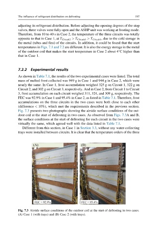
Fig. 7.3 presents two photographs showing the airside surface conditions of the out-
door coil at the start of defrosting in two cases. As observed from Figs. 7.3A and B,
the surface conditions at the start of defrosting for each circuit in the two cases were
virtually the same, which agreed well with the data listed in Table 7.1.
Different from this section, in Case 1 in Section 3.3, without any water-collecting
trays were installed between circuits. It is clear that the temperature orders of the three
Fig. 7.3 Airside surface conditions of the outdoor coil at the start of defrosting in two cases.
(A) Case 1 (with trays) and (B) Case 2 (with trays).