Page 204 - Defrosting for Air Source Heat Pump
P. 204

198                                         Defrosting for Air Source Heat Pump

         circuits for the tube surface and fin center at the same time point are T Circuit 1 >
         T Circuit 2 > T Circuit 3, from 80 s into the defrosting operation to termination, as shown
         in Figs. 3.13 and 3.16. In this section, the same parameters in the two cases were mea-
         sured and presented in Figs. 7.4–7.7, but with water-collecting trays installed between
         circuits. In all these figures, for their time (horizontal) axis, 80 s is the chosen starting


                     28
                                Circuit 1   Circuit 2   Circuit 3
                     24
                                          T  > T  > T 1
                                              3
                                           2
                     20
                    Tube surface temperature ( o C)  16 8  o
                     12


                            (T  – T)  = 2.8 C
                             2
                                1 max
                      4
                                            125 s      185 s
                      0
                       80     100    120    140    160    180     200
                                           Time (s)
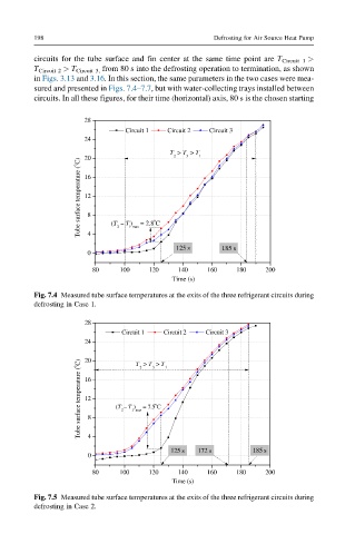
         Fig. 7.4 Measured tube surface temperatures at the exits of the three refrigerant circuits during
         defrosting in Case 1.
                      28
                               Circuit 1     Circuit 2     Circuit 3
                      24          T  > T  > T 1

                      20
                    Tube surface temperature ( o C)  16 8  (T  – T )  = 7.5 C
                                      3
                                   2

                      12
                                       o
                               2
                                 1 max

                      4
                                          125 s  172 s        185 s
                      0
                       80     100    120    140    160    180    200
                                           Time (s)
         Fig. 7.5 Measured tube surface temperatures at the exits of the three refrigerant circuits during
         defrosting in Case 2.
   199   200   201   202   203   204   205   206   207   208   209