
Page 291 - Defrosting for Air Source Heat Pump
P. 291
Defrosting control strategy 285
5 min, the frost accumulation increased 128 g, or 15.9%, from Case 1 to Case 2. How-
ever, the increase of frost accumulation was only 73 g, or 7.3%, from Case 4 to Case 5.
Additionally, the defrosting duration is also not at a positive proportional relationship
with the total frost accumulation. The increased frost accumulation prolonged the
defrosting duration, but the main difference comes at the preheating stage during
defrosting. When the frost accumulation is 805 g in Case 1, the preheating stage cost
35 s while it takes 96 s for the frost accumulation to reach 1074 g in Case 5. Finally, in
view of system stability and indoor thermal comfort, the system performance would
be degraded when frost accumulation was more than 933 g. In view of defrosting per-
formance, the defrosting efficiency also reached its peak at 51.80% when the frost
accumulation was at 933 g. As demonstrated, frost accumulation is the most funda-
mental reference parameter for initiation defrosting control in an ASHP unit with
the frost evenly distributed and the melted frost locally drained. Meanwhile, the
time-based initiation defrosting control was optimized with this method, and thus
the potential energy waste was expected to be saved.
9.4 Termination of defrosting control
In practical applications, an RCD operation can be started based on the surface tem-
perature of an outdoor coil, the pressure difference across an outdoor coil, or time.
Among them, terminating a defrosting operation based on the surface temperature
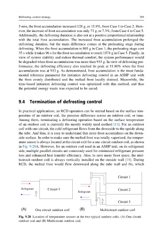
of an outdoor coil is currently the mostly widely used method [11]. For an outdoor
coil with one circuit, the cold refrigerant flows from the downside to the upside along
the tube. And thus, it is easy to understand that more frost accumulates on the down-
side surface. In order to make sure the melted frost was totally vaporized, the temper-
ature sensor is always located at the circuit exit for a one-circuit outdoor coil, as shown
in Fig. 9.28A. However, for an outdoor coil used in an ASHP unit, on its refrigerant
side, multiple parallel circuits are commonly used for minimized refrigerant pressure
loss and enhanced heat transfer efficiency. Also, to save more floor space, the mul-
ticircuit outdoor coil is always vertically installed on the outside wall [18]. During
RCD, the melted frost would flow downward along the tube wall and fin, which
(A) (B)
Fig. 9.28 Location of temperature sensors at the two typical outdoor coils. (A) One circuit
outdoor coil and (B) Multicircuit outdoor coil.