
Page 294 - Defrosting for Air Source Heat Pump
P. 294
288 Defrosting for Air Source Heat Pump
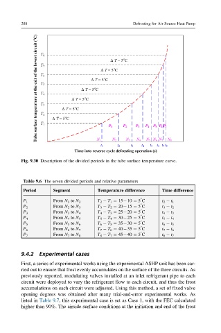
Fig. 9.30 Description of the divided periods in the tube surface temperature curve.
Table 9.6 The seven divided periods and relative parameters
Period Segment Temperature difference Time difference
°
T 2 T 1 ¼ 15 10 ¼ 5 C
P 1 From N 1 to N 2 t 2 t 1
°
T 3 T 2 ¼ 20 15 ¼ 5 C
P 2 From N 2 to N 3 t 3 t 2
°
T 4 T 3 ¼ 25 20 ¼ 5 C
P 3 From N 3 to N 4 t 4 t 3
°
T 5 T 4 ¼ 30 25 ¼ 5 C
P 4 From N 4 to N 5 t 5 t 4
°
T 6 T 5 ¼ 35 30 ¼ 5 C
P 5 From N 5 to N 6 t 6 t 5
°
T 7 T 6 ¼ 40 35 ¼ 5 C
P 6 From N 6 to N 7 t 7 t 6
°
P 7 From N 7 to N 8 T 8 T 7 ¼ 45 40 ¼ 5 C t 8 t 7
9.4.2 Experimental cases
First, a series of experimental works using the experimental ASHP unit has been car-
ried out to ensure that frost evenly accumulates on the surface of the three circuits. As
previously reported, modulating valves installed at an inlet refrigerant pipe to each
circuit were deployed to vary the refrigerant flow to each circuit, and thus the frost
accumulations on each circuit were adjusted. Using this method, a set of fixed valve
opening degrees was obtained after many trial-and-error experimental works. As
listed in Table 9.7, this experimental case is set as Case 1, with the FEC calculated
higher than 90%. The airside surface conditions at the initiation and end of the frost