
Page 634 - Design for Six Sigma a Roadmap for Product Development
P. 634
Tolerance Design 587
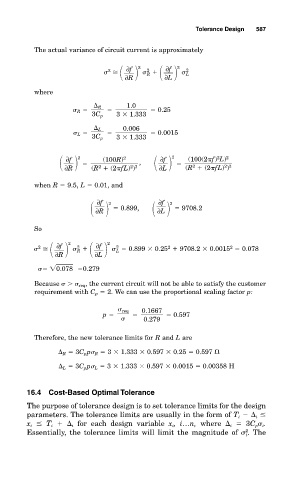
The actual variance of circuit current is approximately
2 2 2 2
∂f
∂f
2
L
R
∂L
∂R
where
1.0
R
R 0.25
3C p 3
1.333
0.006
L
L 0.0015
3C p 3
1.333
2 , 2
2
2
2
∂f
(100(2 f) L)
(100R)
∂f
2
2
2 3
2 3
∂R (R (2 fL) ) ∂L (R (2 fL) )
when R 9.5, L 0.01, and
∂f
∂f
2 0.899, 2 9708.2
∂L
∂R
So
2 2 2 2 2 2
∂f
∂f
2
0.899
0.25 9708.2
0.0015 0.078
L
R
∂R ∂L
0.078 0.279
Because req , the current circuit will not be able to satisfy the customer
requirement with C p 2. We can use the proportional scaling factor p:
req 0.1667
p 0.597
0.279
Therefore, the new tolerance limits for R and L are
R 3C p p R 3
1.333
0.597
0.25 0.597
L 3C p p L 3
1.333
0.597
0.0015 0.00358 H
16.4 Cost-Based Optimal Tolerance
The purpose of tolerance design is to set tolerance limits for the design
parameters. The tolerance limits are usually in the form of T i i
x i T i i for each design variable x i , i…n, where i 3C p i .
2
Essentially, the tolerance limits will limit the magnitude of . The
i