
Page 149 - Dynamic Vision for Perception and Control of Motion
P. 149
5.2 Efficient Extraction of Oriented Edge Features 133
from the mask direction or to slightly curving edges; image pixels under the zero-
mask elements need not be touched, of course, since their weight in the mask van-
ishes.
For efficient computation of correlations, search direction should be either hori-
zontal (in the y-direction, rows, dash-dotted arrow in the figure) or vertical (in the
z-direction, columns); diagonal searches have also been used, initially, but because
of the square-root-of-2 effect in spacing, when proceeding in diagonal search direc-
tion, they have not gained acceptance. The wider the masks chosen, the more angu-
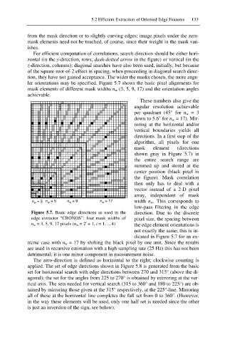
lar orientations may be specified. Figure 5.7 shows the basic pixel alignments for
mask elements of different mask widths n w (3, 5, 9, 17) and the orientation angles
achievable.
These numbers also give the
angular resolution achievable
per quadrant (45° for n w = 3
down to 5.6° for n w = 17). Mir-
roring at the horizontal and/or
vertical boundaries yields all
directions. In a first step of the
algorithm, all pixels for one
mask element (directions
shown gray in Figure 5.7) in
the entire search range are
summed up and stored at the
center position (black pixel in
the figure). Mask correlation
then only has to deal with a
vector instead of a 2-D pixel
array, independent of mask
n w = 3 n w = 5 n w = 9 n w = 17 width n w. This corresponds to
low-pass filtering in the edge
Figure 5.7. Basic edge directions as used in the direction. Due to the discrete
edge extractor “CRONOS”: four mask widths of pixel size, the spacing between
i
n w = 3, 5, 9, 17 pixels (n w = 2 + 1, i = 1, …4) the edge element orientations is
not exactly the same; this is in-
dicated in Figure 5.7 for an ex-
treme case with n w = 17 by shifting the black pixel by one unit. Since the results
are used in recursive estimation with a high sampling rate (25 Hz) this has not been
detrimental; it is one minor component in measurement noise.
The zero-direction is defined as horizontal to the right; clockwise counting is
applied. The set of edge directions shown in Figure 5.8 is generated from the basic
set for horizontal search with edge directions between 270 and 315° (above the di-
agonal); the set for the angles from 225 to 270° is obtained by mirroring at the ver-
tical axis. The sets needed for vertical search (315 to 360° and 180 to 225°) are ob-
tained by mirroring those given at the 315° respectively, at the 225°-line. Mirroring
all of these at the horizontal line completes the full set from 0 to 360°. (However,
in the way these elements will be used, only one half set is needed since the other
is just an inversion of the sign, see below).