
Page 152 - Dynamic Vision for Perception and Control of Motion
P. 152
136 5 Extraction of Visual Features
by experience in visually similar environments. From these considerations, generic
edge extraction mask sets for specific problems have resulted. In Figure 5.11, some
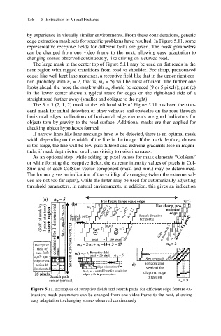
representative receptive fields for different tasks are given. The mask parameters
can be changed from one video frame to the next, allowing easy adaptation to
changing scenes observed continuously, like driving on a curved road.
The large mask in the center top of Figure 5.11 may be used on dirt roads in the
near region with ragged transitions from road to shoulder. For sharp, pronounced
edges like well-kept lane markings, a receptive field like that in the upper right cor-
ner (probably with n d = 2, that is, m d = 5) will be most efficient. The further one
looks ahead, the more the mask width n w should be reduced (9 or 5 pixels); part (c)
in the lower center shows a typical mask for edges on the right-hand side of a
straight road further away (smaller and oblique to the right).
The 5 × 5 (2, 1, 2) mask at the left hand side of Figure 5.11 has been the stan-
dard mask for initial detection of other vehicles and obstacles on the road through
horizontal edges; collections of horizontal edge elements are good indicators for
objects torn by gravity to the road surface. Additional masks are then applied for
checking object hypotheses formed.
If narrow lines like lane markings have to be detected, there is an optimal mask
width depending on the width of the line in the image: If the mask depth n d chosen
is too large, the line will be low-pass-filtered and extreme gradients lose in magni-
tude; if mask depth is too small, sensitivity to noise increases.
As an optional step, while adding up pixel values for mask elements “ColSum”
or while forming the receptive fields, the extreme intensity values of pixels in Col-
Sum and of each ColSum vector component (max. and min.) may be determined.
The former gives an indication of the validity of averaging (when the extreme val-
ues are not too far apart), while the latter may be used for automatically adjusting
threshold parameters. In natural environments, in addition, this gives an indication
(a) n w = 5 n =1
For fuzzy large scale edge For sharp, pro - d
(Shift of mask by 1 pixel at a time) search region condensed to 1-dimensional (averaged) vector Search path n d =7 field of mask: n w =17 n = 17 Search direction nounced
(b)
Receptive
n w = 17
edge
(total = 51 pixel)
center
horizontal
+ -
0
n 0 =3
n d =7
-
+
total = 289 pixel
Receptive Search direction vertical m = 2·n + n =14 + 3 = 17 Edge orientation 5 Edge orientation 5 m d = 3
d
0
d
field of
size 5×5: (c) n = 2; Receptive field orientation 8
n d =2; n 0 =1; 0 total = 30 pixel n w = 5 Search path Edge
edge orien- + + + 0 0 -
tation16 0 + - d) horizontal or
(horizontal) - - Edge orientation 4 vertical for
n 0=2; m d = 6 : small base for localizing
25 pixels edges with larger curvature diagonal edge
Search path direction
center (vertical) n w = 9
Figure 5.11. Examples of receptive fields and search paths for efficient edge feature ex-
traction; mask parameters can be changed from one video-frame to the next, allowing
easy adaptation to changing scenes observed continuously