
Page 162 - Electrical Properties of Materials
P. 162
144 Semiconductors
the passage of carriers? Not normally. When, in the circuit of Fig. 8.12, we
μ= σ/Ne close the switch the electrons acquire an ordered motion everywhere. Those
that happen to be at point C when the switch is closed will arrive at point A
A C
n some time later, but we have no means of learning when. From the moment
Semiconductor the switch is closed, the flow of electrons is uniform at both points, C and
A. What we need is a circuit in which carriers can be launched at one point
+ Switch
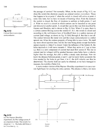
and detected at another point. A circuit that can do this was first described by
Haynes and Shockley and is shown in Fig. 8.13(a). When S is open, there is
Fig. 8.12 a certain current flowing across the resistor R.At t 1 the switch is closed and
Current flow in an n-type according to the well-known laws of Kirchhoff there is a sudden increase of
semiconductor. current [and voltage, as shown in Fig. 8.13(b)] through R. But that is not all.
The contact between the metal wire and the n-type semiconductor is a rather
special one. It has the curious property of being able to inject holes. We shall
say more about injection later, but for the time being please accept that holes
appear at point A, when S is closed. Under the influence of the battery B 1 the
holes injected at A will move towards C. When they arrive at C (say at time
t 2 ), there is a new component of current that must flow across R. The rise in
current (and in voltage) will be gradual because some holes have a velocity
higher than the average, but after a while a steady state develops. Now we
know the distance between points A and C, and we know fairly accurately the
time needed by the holes to get from A to C; the drift velocity can thus be
determined. The electric field can easily be obtained, so we have managed to
measure, the mobility (Table 8.4).
A more modern version of the Haynes–Shockley experiment is to use a nar-
row light beam for exciting the extra carriers. The physics is then a lot more
+ S +
Oscilloscope
R V
A C
n
+ B 1
(a)
V
Fig. 8.13
(a) The Haynes–Shockley
experiment. (b) The voltage across R (b) Time
t t
as a function of time. The switch S is 1 2
closed at t = t 1 . The holes drift from A Switch
to C in a time t 2 – t 1 . closes