
Page 164 - Electrical Properties of Materials
P. 164
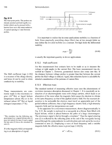
146                           Semiconductors

                                                                                      Voltmeter
                                                                                      leads
                                       Current
     Fig. 8.14                         leads
     The four-point probe. The probes are                                    Probe holder
     sharply pointed and held rigidly in a
                                                          1    2   3   4  Semiconductor sample
     holder which can be pressed with a
     known force on to the semiconductor.
     A typical spacing is 1 mm between
     probes.                                                                Table

                                     It is important to realize that in some applications mobility is a function of
                                   field. Since practically everything obeys Ohm’s law at low enough fields we
                                   may define the low field mobility as a constant. For high fields the differential
                                   mobility

                                                                   dv D
                                                             μ diff =                       (8.60)
                                                                   dE
                                   is usually the important quantity in device applications.

                                   8.10.2  Hall coefficient

                                   For this measurement four contacts have to be made so as to measure the
                                   voltage at right angles to the current flow. The basic measurement was de-
                                   scribed in Chapter 1. However, geometrical factors also come into this. If
     The Hall coefficient [eqn (1.20)]  the distance between voltage probes is greater than that between the current
     is a measure of the charge density,  probes the Hall voltage is reduced. Again, this reduction factor is calculable by
     and hence it can be used to relate  detailed consideration of the patterns of current flow.
     conductivity to mobility.
                                   8.10.3  Effective mass

                                   The standard method of measuring effective mass uses the phenomenon of
     These measurements are com-   cyclotron resonance absorption discussed in Chapter 1. It is essentially an in-
     monly made in the microwave re-  teraction of an electromagnetic wave with charge carriers, which leads to an
            10
     gion (10 Hz) at liquid helium  absorption of the wave when the magnetic field causes the electron to vibrate
     temperature (about 4 K) or in the  at the same frequency as that of the applied electric field. For the resonant ab-
                    13
     infrared (about 10 Hz) at liquid  sorption to be noticeable the electron must travel an appreciable part of the
     nitrogen temperature (77 K).  period without collisions; thus a high-frequency electric field, a high-intensity
                                   magnetic field, and low temperatures are used.
                                     In the apparatus for a microwave measurement, shown diagrammatically in
                                   Fig. 8.15, the sample is enclosed in a waveguide in a Dewar flask filled with
                                   liquid helium, which is placed between the poles of a large electromagnet.
                                                                            ∗
     ∗  The circulator has the following ma-  The microwave signal is fed in through a circulator. Thus the signal entering
     gical properties: a signal fed into arm (1)  arm (2) is reflected by the reflecting plate at the end of the waveguide having
     goes out entirely by arm (2) and a signal  passed through the semiconductor in each direction and ends up in the receiver
     fed into arm (2) leaves the circulator by
     arm (3).                      connected to arm (3). Employing a wave of fixed frequency and a variable
                                   magnetic field; the effective mass is given [eqn (1.64)] by
     B is the magnetic field correspond-
                                                              ∗
     ing to an absorption of signal.                         m = eB/ω c .                   (8.61)