
Page 221 - Electrical Properties of Materials
P. 221
The Gunn effect 203
U
U
A
(ii) (i)
0 d
(ii)
(i)
A
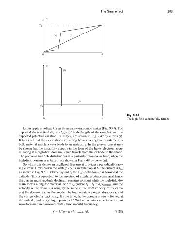
Fig. 9.49
0 d The high-field domain fully formed.
Let us apply a voltage U A in the negative-resistance region (Fig. 9.48). The
expected electric field E A = U A /d (d is the length of the sample), and the
expected potential variation, U = E A x, are shown in Fig. 9.49 by curves (i).
It turns out that the expectations are wrong because a negative resistance in a
bulk material nearly always leads to an instability. In the present case it may
be shown that the instability appears in the form of the heavy electrons accu-
mulating in a high-field domain, which travels from the cathode to the anode.
The potential and field distributions at a particular moment in time, when the
high-field domain is in transit, are shown in Fig. 9.49 by curve (ii).
So why is this device an oscillator? Because it provides a periodically vary-
ing current. How? When the voltage U A is switched on at t 0 , the current is I A ,
as shown in Fig. 9.50. Between t 0 and t 1 the high-field domain is formed at the
cathode. This is equivalent to the insertion of a high resistance material, hence
the current must suddenly decline. It remains constant while the high-field do-
main moves along the material. At t = t 2 (where t 2 – t 1 = d/v domain , and the
velocity of the domain is roughly the same as the drift velocity of the carri-
ers) the domain reaches the anode. The high resistance region disappears, and
the current climbs back to I A . By the time, t 3 , the domain is newly formed at
the cathode, and everything repeats itself. We have obtained a periodic current
waveform rich in harmonics with a fundamental frequency,
~
f =1/(t 3 – t 1 ) = v domain /d. (9.28)