
Page 217 - Electrical Properties of Materials
P. 217
Charge-coupled devices 199
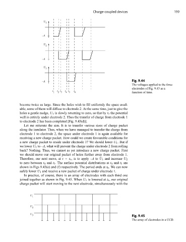
U
1
–A
U
2
–A
U
3
–A Fig. 9.44
The voltages applied to the three
electrodes of Fig. 9.43 as a
t t t t t t
1 2 3 4 5 6 function of time.
become twice as large. Since the holes wish to fill uniformly the space avail-
able, some of them will diffuse to electrode 2. At the same time, just to give the
holes a gentle nudge, U 1 is slowly returning to zero, so that by t 3 the potential
well is entirely under electrode 2. Thus the transfer of charge from electrode 1
to electrode 2 has been completed [Fig. 9.43(d)].
Let me reiterate the aim. It is to transfer various sizes of charge packet
along the insulator. Thus, when we have managed to transfer the charge from
electrode 1 to electrode 2, the space under electrode 1 is again available for
receiving a new charge packet. How could we create favourable conditions for
a new charge packet to reside under electrode 1? We should lower U 1 .But if
we lower U 1 to –A, what will prevent the charge under electrode 2 from rolling
back? Nothing. Thus, we cannot as yet introduce a new charge packet. First
we should move our original packet of holes further away from electrode 1.
Therefore, our next move, at t = t 4 , is to apply –A to U 3 and increase U 2
to zero between t 4 and t 5 . The surface potential distributions at t 4 and t 5 are
shown in Figs 9.43(e) and (f) respectively. The period ends at t 6 . We can now
safely lower U 1 and receive a new packet of charge under electrode 1.
In practice, of course, there is an array of electrodes with each third one
joined together as shown in Fig. 9.45. When U 1 is lowered at t 6 , our original
charge packet will start moving to the next electrode, simultaneously with the
U
1
U
2
U
3 Fig. 9.45
The array of electrodes in a CCD.