
Page 229 - Electrical Properties of Materials
P. 229
Plasma etching 211
described there, is an isotropic process—acid reacts sideways as well as down- ∗ Gas discharge physics has been a fa-
wards, so the sidewalls of channels are eaten away, making a, the minimum vourite topic for scientists for well over
feature size, larger. This is worsened if hot hydrofluoric acid is used to speed a century. Irving Langmuir, who was a
pioneer of diagnosing gas discharges, es-
things up or to dissolve silicon nitride layers (which have been used to improve pecially with probes, coined the word
MOST performance). It can damage the edge of the photoresist. There are ‘plasma’ about 87 years ago at the time
skilled handling operations involved in the liquid (wet) chemistry, so that oper- of writing (2013). The subject got an im-
mense boost about 60 years ago when
ator skills were found to affect device yields. Improvements were needed as a
the possibility of controlled fusion of hy-
got below 1 μm. Plasma processing was introduced, a dry process, more auto- drogen isotopes was proposed to solve
∗
mated. We first mentioned plasma physics in Section 1.7 and it has cropped up our energy problems with no nasty side
several times since then. Usually a gas discharge plasma is about 0.1% ionized products. The science was well estab-
2
lished. E = mc was believed by every-
and so consists mainly of neutral gas atoms or molecules, outnumbering the
one, and all the stars used fusion, in-
ions and electrons. To achieve anisotropic etching we must use a field to direct cluding our sun, which had enabled life
etching ions to the surface, and not to the sidewalls. In the jargon, this is RIE, on earth to be established. It could also
or reactive ion etching. This field can be realized with a d.c. voltage between be man made, as we had the H-bomb,
which at some times had threatened to
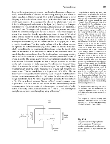
the input and the earthed electrodes (Fig. 9.56). Or this can be done more clev-
finish life on earth. So it seemed only
erly by controlling the gas constituents of the plasma so that the sheath which a development job to get a controllable
forms on the surfaces of the electrodes has a built-in field which influences the fusion energy source. Enormous sums
ions striking the semiconductor slice. The sheath contains positive and negative of money and highly skilled man-hours
have been spent in failing to do this
ions as well as electrons and in practical cases can have a potential difference of
(so far). A by-product is a lot of skilled
several kilovolts. The neutral atoms will slow down the movement of the ions, plasma physicists who have done good
so to increase their mean free path we need a low gas pressure, but we also science, but, unfortunately, almost every
need a high ion density for fast processing. The obvious way to satisfy these discovery has revealed new instabilities
which make it more difficult to contain
criteria is to increase the ionization fraction of the gas. One way of doing this is the hot plasma in its reaction vessel. It
by capacitatively coupling a radio frequency field of quite high power into the looks as if the right size for a fusion re-
†
plasma vessel. This has usually been at a frequency of 13.56 MHz. The ion actor is the size of the sun—much too
density can be increased further by applying a static magnetic field to achieve largetofitintothe LosAlamosdesertor
even the Australian Outback. Thus there
electron cyclotron resonance (Section 1.6) so that the electrons absorb more is a lot of plasma knowledge which can
energy from the r.f. field. An outline diagram of an apparatus for this is shown be separated from fusion plasma physics
‡
in Fig. 9.56. A well-read textbook, Plasma etching, gives the pressure range and instead used to study plasma etching
and cleaning of surfaces.
of gases used as 0.13 to 133 Pa. The reason for this rather arbitrary choice
becomes apparent when we restate it in the previous preferred units of milli- † A frequency allocated by governments
metres of mercury, or torr. It then becomes 10 –3 Torr to 1 Torr, showing that for industrial use. We mentioned this
most plasma engineers were brought up using ‘old money’. frequency, together with 2.45 GHz, in
describing molecular beam epitaxy (Sec-
tion 8.11.5).
‡ M. Sugawara, Plasma etching, fun-
Gas damentals and applications,Serieson
inlet Semiconductor Science and Technology
(Oxford University Press, 1998).
R.F. ~ Field
generator coils
Wafers
Fig. 9.56
Diagrammatic drawing of plasma
etching apparatus. The pressure
monitors and controllers to keep the
Exhaust etchant gases at the required levels are
pump not shown.