
Page 226 - Embedded Microprocessor Systems Real World Design
P. 226
CW DATA BUS >D Q > CW2DATABUS
1
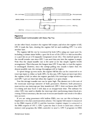
Figure 8.3
Register-Based Communication with Status Flip-Flop.
on the other hand, monitors the register full output; and when the register is full,
CPU 2 reads the byte, clearing the register full bit and enabling CPU 1 to write
another byte.
The register full bit can be monitored by both CPUs using any input port bit,
including a tristate status buffer, a port bit if one of the CPUs is a microcontroller,
or a port bit on an 1/0 expander integrated circuit (IC). This method speeds up
the overall transfer rate since CPU 1 can send data any time the register is empty.
Note that the slowest transfer rate is the same as for the simple register/strobe
arrangement. This is because the longest time CPU 2 may take to read the register
is unchanged. However, since the average polling rate usually is faster than the
slowest possible rate, the average throughput will be higher.
To speed things up even more, the register full bit also can be connected to an
interrupt input to either or both CPUs. In this case, CPU 2 gets an interrupt when
the register is full (or when the register goes full if the interrupt is edge sensitive),
and CPU 1 gets an interrupt when the register is or goes empty.
Now the average transfer rate can be quite high. The slowest rate is the sum of
the worstcase interrupt latencies of both processors. However, both processors
must service one interrupt per byte transferred. CPU 1 does not know what CPU
2 is doing and may flood it with data at an inopportune time. The software for
either CPU may need to disable the interrupt when performing timecritical pro-
cessing. If this is necessary, the decrease in worstcase transfer rate needs to be taken
into account.
If you are using processors with built-in DMA, you can use this technique to
implement a very fast communication scheme. The register full output is connected
to the DMA request of CPU 2, and the inversion (register empty) is connected to
the DMA request of CPU 1. CPU 1 puts the data it needs to send into a block of
memory and programs the DMA controller to send it. CPU 2 programs its DMA
Multiprocessor Systems 207