
Page 228 - Embedded Microprocessor Systems Real World Design
P. 228
REGISTER 1
CW 1 DATA BUS > CWZDATABUS
REGISTER 1
WRITE STROBE REGISTER 1
READ STROBE
FROM CPU 1
FROM CPU 2
REG FULL
TO CPU 2 DMA REQUEST 0
WRITE STROBE
TO SET EOM 1 INTERRUPT EOM 1 INTERRUPT
FROM CW 1 TO CW 2
REGISTER 2
REGISTER 2
READ STROBE WRITE STROBE
FROM CPU 2
FROM CW 1
REGISTER FULL
STATUS BIT
TOCPU 1
REGISTER 2 EMPTY
I TO CPU 2
DMA REQUEST 1
€OM INTERRUPT 2 STROBE TO SET
TO CPU 1 EDM INTERRUPT 2
FROM CPU 2
STROBE TO CLEAR
€OM INTERRUPT 2
FROM CPU 1
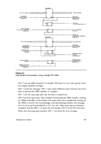
Figure 8.4
Dual 80188 Communication Using a Single CPU DMA.
CPU 2 sets up DMA channel 0 to transfer 256 bytes (or any value greater than
the longest possible message).
CPU 1 sends the message. CPU 1 must allow sufficient time between successive
bytes to permit the DMA transfer to complete.
CPU 1 sets the interrupt after the last byte is transferred.
CPU 2 services interrupt. This includes terminating the DMA transfer, reading
the DMA controller to determine how many bytes were transferred, setting up
the DMA to receive the next package, and determining whether the message
must be processed immediately or if' it can wait. After interrupt processing is
complete and the DMA is set up fm the next transfer, CPU 2 resets the interrupt.
When the interrupt goes inactive, CPU 1 can send the next message.
Multiprocessor Systems 209