
Page 298 - Embedded Microprocessor Systems Real World Design
P. 298
Many CPUs, such as Pentium-class processors, go a step further, integrating a
small cache onto the CPU chip itself. This provides a very fast cache memory,
capable of keeping up with the CPU at full speed. However, since SRAM takes a
significant amount of real estate on the CPU die, on-chip cache memory typically
is smaller than off-chip cache memory. Many designs include both types of cache
memory for maximum performance.
Processors with Multiple Clock Inputs and
Phase-Locked Loops
Many microprocessors need more than one clock input. The AMD SC520 is an
example of this. The SC520 requires two crystals (or external oscillators). One
crystal runs at 32.768kHz and provides a signal to the real-time clock and SDRAM
refresh logic. The SC520 also has a 33MHz input, which provides clocks to the CPU,
PCI bus, and other internal peripherals.
As processor speeds exceed 30MHz or so, it is difficult to get crystals to run
the CPU. Fundamental mode crystals typically are unavailable above 30MHz. The
SC520, in addition to the clocks mentioned, requires 66MHz for the SDRAM
logic and 18.432MHz for the UARTs. Clocks like this are often generated by a
phase-locked loop (PLATA) inside the microprocessor IC. While the complexities of
PLL theory are beyond the scope of this book, a PLL can be thought of as a
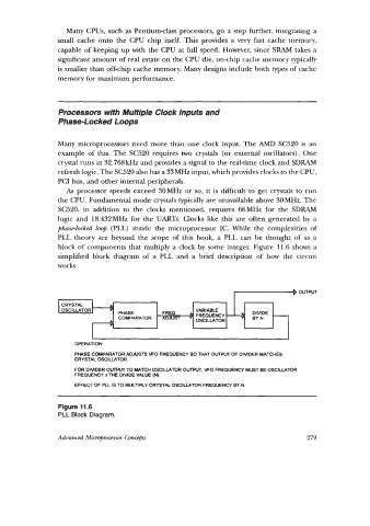
block of components that multiply a clock by some integer. Figure 11.6 shows a
simplified block diagram of a PLL and a brief description of how the circuit
works.
CRYSTAL
OSCILLATOR PHASE FREQ VARIABLE BYN -
FREQUENCY 4
DlVlDE
COMPARATOR ADJUST D
OSCILLATOR
OPERATION.
PHASE COMPARATOR ADJUSTS MO FREQUENCY SO THAT OUTPUT OF DIVIDER MATCHES
CRYSTAL OSCILLATOR.
FOR DIVIDER O W TO MATCH OSCILLATOR OUTPUT. VFO FREQUENCY MUST BE OSCILLATOR
FREQUENCY x THE DIVIDE VALUE (N).
EFFECT OF PLL IS TO MuLnRY CRYSTAL OSCILLATOR FREQUENCY BY N
Figure 11.6
PLL Block Diagram.
Advanced Micropomsor Concgbts 279