
Page 78 - Embedded Microprocessor Systems Real World Design
P. 78
..
28530
80180 PULLUP
CLKOW
-WR , h I -WR
WAC14
-RD , -RD
ADDRESS
UTCH
A1 , DE
A0
Nj
DATA
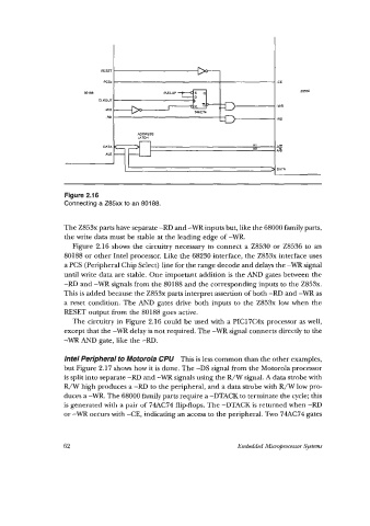
Figure 2.1 6
Connecting a Z85xx to an 80188.
The Z853x parts have separate -RD and -WR inputs but, like the 68000 family parts,
the write data must be stable at the leading edge of -WR.
Figure 2.16 shows the circuitry necessary to connect a 28530 or 28536 to an
80188 or other Intel processor. Like the 68230 interface, the Z853x interface uses
a PCS (Peripheral Chip Select) line for the range decode and delays the -WR signal
until write data are stable. One important addition is the AND gates between the
-RD and -WR signals from the 80188 and the corresponding inputs to the Z853x.
This is added because the Z853x parts interpret assertion of both -RD and -WR as
a reset condition. The AND gates drive both inputs to the Z853x low when the
RESET output from the 80188 goes active.
The circuitry in Figure 2.16 could be used with a PIC17C4x processor as well,
except that the -WR delay is not required. The -WR signal connects directly to the
-WR AND gate, like the -RD.
lntel Peripheral to Motorola CPU This is less common than the other examples,
but Figure 2.17 shows how it is done. The -DS signal firom the Motorola processor
is split into separate -RD and -WR signals using the R/W signal. A data strobe with
R/W high produces a -RD to the peripheral, and a data strobe with R/W low pro-
duces a -WR. The 68000 family parts require a -DTACK to terminate the cycle; this
is generated with a pair of 74AC74 flip-flops. The -DTACK is returned when -RD
or -WR occurs with -CE, indicating an access to the peripheral. Two 74AC74 gates
62 Embedded Microprocessor Systems