
Page 83 - Embedded Microprocessor Systems Real World Design
P. 83
I
-RD 0
) DATA
-WR 0
-BHE 0 -cs
I1 I 4 - W -0E R
A0
BHE A0
0 0 BOTHBYTESENABLED
0 1 UPPERBYTEENABLED
1 0 LOWER BYTE ENABLED
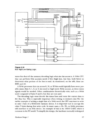
Figure 2.19
Bus High/Low Gating Logic.
status bits that tell the memory decoding logic what size the access is. A 16-bit CPU
that can perform &bit accesses needs 2 bits (high byte, low byte, both bytes) to
determine what portion of the bus is used. As mentioned, on the x86, these are
BHE and AO.
A 32-bit processor that can access 8,16, or 32 bits would typically have seven pos
sible states (byte 0, 1, 2, or 3, low word or high word, 32 bit access), so three status
signals would be needed. Other combinations theoretically exist, such as a lGbit
word composed of bytes 0 and 2, but they are not used.
The decoding logic must decode the status lines and route the correct data to
the data bus. This is especially important when writing to memory. Just like the
earlier example of writing a single byte of a lGbit word, the CPU may want to write
to only 1 byte of a 32-bit-wide memory device. It is important not to corrupt the
other 3 bytes during that write cycle. In many cases, a 16-, 32-, or 64bit processor
will interface to an &bit device. An example of this is the 16550 UART, which is
common in the PC world. To simplify the design, the hardware normally is designed
Hardware Design 1 67