
Page 250 - Academic Press Encyclopedia of Physical Science and Technology 3rd Analytical Chemistry
P. 250
P1: GRB/GWT P2: GPJ/GAX QC: GAE/FYD Final Pages
Encyclopedia of Physical Science and Technology EN008M-395 June 29, 2001 15:52
Magnetic Resonance in Medicine 975
an appropriate envelope function. One useful modulation
function is sin t / t . Here, is an audio frequency that
is high enough to permit sin t to go through a few cy-
cles during the time the excitation pulse is being applied.
Using this or slightly more complicated modulation func-
tions, a rectangular slice profile can be approached. The
stronger the gradient applied during excitation, the thin-
ner the resultant slice will be. Typical gradient strengths
are of the order of 1 G/cm or less. Typical durations for
the excitation pulses are in the range from 1 to 3 msec.
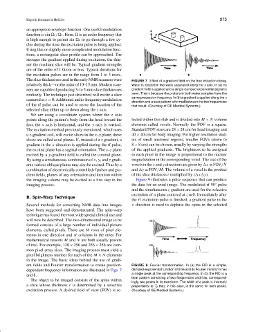
The slice thicknesses used in the early NMR scanners were FIGURE 7 Effect of a gradient field on the free induction decay.
relatively thick—on the order of 10–15 mm. Modern scan- Water is located in two wells separated along the x axis. In (a) no
ners are capable of producing 3- to 5-mm slice thicknesses gradient field is applied and a single damped exponential signal is
routinely. The technique just described will excite a slice seen. This is because the protons in both water samples have the
same precession frequency. In (b) a gradient is applied along the x
centered at z = 0. Additional audio-frequency modulation
direction and a beat pattern is formed between the two frequencies
of the rf pulse can be used to move the location of the that result. (Courtesy of GE Medical Systems.)
selected slice either up or down along the z axis.
We are using a coordinate system where the z axis
points along the patient’s body from the head toward the lected within this slab and is divided into M × N volume
feet, the x axis is horizontal, and the y axis is vertical. elements called voxels. Normally the FOV is a square.
The excitation method previously mentioned, which uses Standard FOV sizes are 24 × 24 cm for head imaging and
a z-gradient coil, will excite slices in the x–y plane; these 40 × 40 cm for body imaging. For higher resolution stud-
slices are called axial planes. If, instead of a z gradient, a ies of small anatomic regions, smaller FOVs (down to
gradient in the x direction is applied during the rf pulse, 8 × 8 cm) can be chosen, usually by varying the strengths
the excited plane has a sagittal orientation. The x–z plane of the applied gradients. The brightness to be assigned
excited by a y-gradient field is called the coronal plane. to each pixel in the image is proportional to the nuclear
By using a simultaneous combination of x, y, and z gradi- magnetization in the corresponding voxel. The size of the
ents various oblique planes may also be excited. Thus by a voxels in the x and y directions are given by x = FOV/N
combination of electronically controlled rf pulses and gra- and y = FOV/M. The volume of a voxel is the product
dient fields, planes of any orientation and location within of the slice thickness t multiplied by ( x y).
the imaging volume may be excited as a first step in the Figure 9 illustrates a pulse sequence that can produce
◦
imaging process. the data for an axial image. The modulated rf 90 pulse
and the simultaneous z gradient are used for the selective
excitation of a plane centered at z = 0. Immediately after
B. Spin-Warp Technique
the rf excitation pulse is finished, a gradient pulse in the
Several methods for converting NMR data into images x direction is used to dephase the spins in the selected
have been suggested and demonstrated. The spin-warp
technique has found the most wide spread clinical use and
will now be described. The two-dimensional image to be
formed consists of a large number of individual picture
elements, called pixels. There are M rows of pixel ele-
ments in one direction and N columns in the other. For
mathematical reasons M and N are both usually powers
of two. For example, 128 × 256 and 256 × 256 are com-
mon pixel array sizes. The imaging process must yield a
pixel brightness number for each of the M × N elements
in the image. The basic ideas behind the use of gradi-
ent fields and Fourier transformation to create position- FIGURE 8 Fourier transformation. In (a) the FID is a simple,
dependent frequency information are illustrated in Figs. 7 damped-exponential function of time and its Fourier transform has
and 8. a single peak at the corresponding frequency. In (b) the FID is a
beat pattern consisting of two frequencies and has, correspond-
The object to be imaged consists of the spins within
ingly, two peaks in its transform. The width of a peak is inversely
a slice whose thickness t is determined by a selective proportional to T 2 that, in this case, is the same for both peaks.
excitation process. A desired field of view (FOV) is se- (Courtesy of GE Medical Systems.)