
Page 251 - Academic Press Encyclopedia of Physical Science and Technology 3rd Analytical Chemistry
P. 251
P1: GRB/GWT P2: GPJ/GAX QC: GAE/FYD Final Pages
Encyclopedia of Physical Science and Technology EN008M-395 June 29, 2001 15:52
976 Magnetic Resonance in Medicine
By combining Eqs. (10) and (11), the extent of the voxel
in the x direction is given by
R
x = FOV/N = 2π T s γ G (12)
x
After a time T R measured from the beginning of the se-
lective excitation pulse, the process is repeated for a total
of M cycles, each of which uses a different value for the
phase-encoding gradient. After this process is complete,
a M × N array of digitally sampled data is available in
the computer memory. This data can be converted by a
two-dimensional Fourier transform technique into M × N
pixelbrightnessnumbers.Thesenumberscanbedisplayed
as an image, which can be viewed either on a cathode ray
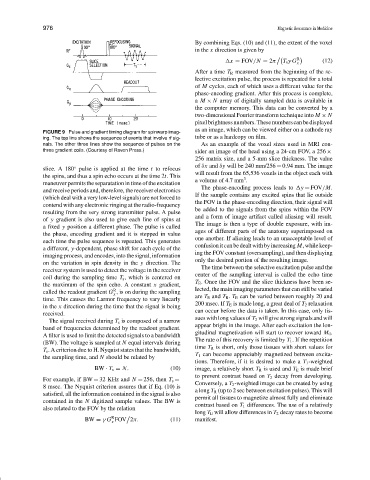
FIGURE 9 Pulse and gradient timing diagram for spinwarp imag-
ing. The top line shows the sequence of events that involve rf sig- tube or as a hardcopy on film.
nals. The other three lines show the sequence of pulses on the As an example of the voxel sizes used in MRI con-
three gradient coils. (Courtesy of Raven Press.)
sider an image of the head using a 24-cm FOV, a 256 ×
256 matrix size, and a 5-mm slice thickness. The value
of δx and δy will be 240 mm/256 = 0.94 mm. The image
◦
slice. A 180 pulse is applied at the time t to refocus
will result from the 65,536 voxels in the object each with
the spins, and thus a spin echo occurs at the time 2t. This 3
a volume of 4.7 mm .
maneuver permits the separatation in time of the excitation
The phase-encoding process leads to y = FOV/M.
and receive periods and, therefore, the receiver electronics
If the sample contains any excited spins that lie outside
(which deal with a very low-level signals) are not forced to
the FOV in the phase-encoding direction, their signal will
contend with any electronic ringing at the radio-frequency
be added to the signals from the spins within the FOV
resulting from the very strong transmitter pulse. A pulse
and a form of image artifact called aliasing will result.
of y gradient is also used to give each line of spins at
The image is then a type of double exposure, with im-
a fixed y position a different phase. The pulse is called
ages of different parts of the anatomy superimposed on
the phase, encoding gradient and it is stepped in value
one another. If aliasing leads to an unacceptable level of
each time the pulse sequence is repeated. This generates
confusionitcanbedealtwithbyincreasing M,whilekeep-
a different, y-dependent, phase shift for each cycle of the
ing the FOV constant (oversampling), and then displaying
imaging process, and encodes, into the signal, information
only the desired portion of the resulting image.
on the variation in spin density in the y direction. The
The time between the selective excitation pulse and the
receiver system is used to detect the voltage in the receiver
center of the sampling interval is called the echo time
coil during the sampling time T s , which is centered on
T E . Once the FOV and the slice thickness have been se-
the maximum of the spin echo. A constant x gradient,
R
called the readout gradient G , is on during the sampling lected, the main imaging parameters that can still be varied
x
time. This causes the Larmor frequency to vary linearly are T E and T R . T E can be varied between roughly 20 and
200 msec. If T E is made long, a great deal of T 2 relaxation
in the x direction during the time that the signal is being
can occur before the data is taken. In this case, only tis-
received.
sues with long values of T 2 will give strong signals and will
The signal received during T s is composed of a narrow
appear bright in the image. After each excitation the lon-
band of frequencies determined by the readout gradient.
gitudinal magnetization will start to recover toward M 0 .
A filter is used to limit the detected signals to a bandwidth
The rate of this recovery is limited by T 1 . If the repetition
(BW). The voltage is sampled at N equal intervals during
time T R is short, only those tissues with short values for
T s . A criterion due to H. Nyquist states that the bandwidth,
T 1 can become appreciably magnetized between excita-
the sampling time, and N should be related by
tions. Therefore, if it is desired to make a T 1 -weighted
BW · T s = N. (10) image, a relatively short T R is used and T E is made brief
to prevent contrast based on T 2 decay from developing.
For example, if BW = 32 KHz and N = 256, then T s =
Conversely, a T 2 -weighted image can be created by using
8 msec. The Nyquist criterion assures that if Eq. (10) is
a long T R (up to 2 sec between excitation pulses). This will
satisfied, all the information contained in the signal is also
permit all tissues to magnetize almost fully and eliminate
contained in the N digitized sample values. The BW is
contrast based on T 1 differences. The use of a relatively
also related to the FOV by the relation
long T E will allow differences in T 2 decay rates to become
R
BW = γ G FOV 2π. (11) manifest.
x