
Page 49 - Engineered Interfaces in Fiber Reinforced Composites
P. 49
32 Engineered interfaces in fiber reinforced composites
bc
HSCH CH CH SIIOCH~)~
c ‘b2a2
(a)
3.k
100
PPM
0
200
150
50
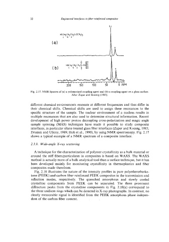
Fig. 2.17. NMR Spectra of (a) a polymerized coupling agent and (b) a coupling agent on a glass surface.
After Zaper and Koenig (1985).
different chemical environments resonate at different frequencies and thus differ in
their chemical shifts. Chemical shifts are used to assign these resonances to the
specific structure of the sample. The nuclear environment of a nucleus results in
multiple resonances that are also used to determine structural information. Recent
development of high power proton decoupling cross-polarization and magic angle
sample spinning (MAS) techniques have made it possible to study composite
interfaces, in particular silane treated glass fiber interfaces (Zaper and Koenig, 1985;
Drumm and Ulicny, 1989; Hoh et al., 1990), by using NMR spectroscopy. Fig. 2.17
shows a typical example of a NMR spectrum of a composite interface.
2.3.9. Wide-angle X-ray scattering
A technique for the characterization of polymer crystallinity as a bulk material or
around the stiff fibers/particulates in composites is based on WAXS. The WAXS
method is actually more of a bulk analytical tool than a surface technique, but it has
been developed mainly for monitoring crystallinity in thermoplastics and fiber
composites made therefrom.
Fig. 2.18 illustrates the nature of the intensity profiles in pure polyetheretherke-
tone (PEEK) and carbon fiber reinforced PEEK composites in the transmission and
reflection modes, respectively. The quenched amorphous and slowly cooled
crystalline components from PEEK can be separated. The three prominent
diffraction peaks from the crystalline components in Fig. 2.18(a) correspond to
the three uniform rings which can be detected in X-ray photographs. In contrast, no
clearly measurable signal is identified from the PEEK amorphous phase indepen-
dent of the carbon fiber content.