
Page 367 - Engineering Digital Design
P. 367
338 CHAPTER 8 / ARITHMETIC DEVICES AND ARITHMETIC LOGIC UNITS (ALUs)
A(H)
;^O—s H)
(
HA
FA
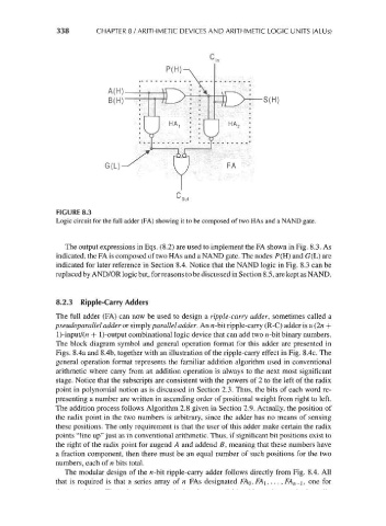
FIGURE 8.3
Logic circuit for the full adder (FA) showing it to be composed of two HAs and a NAND gate.
The output expressions in Eqs. (8.2) are used to implement the FA shown in Fig. 8.3. As
indicated, the FA is composed of two HAs and a NAND gate. The nodes P(H) and G(L) are
indicated for later reference in Section 8.4. Notice that the NAND logic in Fig. 8.3 can be
replaced by AND/OR logic but, for reasons to be discussed in Section 8.5, are kept as NAND.
8.2.3 Ripple-Carry Adders
The full adder (FA) can now be used to design a ripple-carry adder, sometimes called a
pseudoparallel adder or simply parallel adder. An n-bit ripple-carry (R-C) adder is a (2n +
l)-input/(n + l)-output combinational logic device that can add two n-bit binary numbers.
The block diagram symbol and general operation format for this adder are presented in
Figs. 8.4a and 8.4b, together with an illustration of the ripple-carry effect in Fig. 8.4c. The
general operation format represents the familiar addition algorithm used in conventional
arithmetic where carry from an addition operation is always to the next most significant
stage. Notice that the subscripts are consistent with the powers of 2 to the left of the radix
point in polynomial notion as is discussed in Section 2.3. Thus, the bits of each word re-
presenting a number are written in ascending order of positional weight from right to left.
The addition process follows Algorithm 2.8 given in Section 2.9. Actually, the position of
the radix point in the two numbers is arbitrary, since the adder has no means of sensing
these positions. The only requirement is that the user of this adder make certain the radix
points "line up" just as in conventional arithmetic. Thus, if significant bit positions exist to
the right of the radix point for augend A and addend B, meaning that these numbers have
a fraction component, then there must be an equal number of such positions for the two
numbers, each of n bits total.
The modular design of the n-bit ripple-carry adder follows directly from Fig. 8.4. All
that is required is that a series array of n FAs designated MO, FA\, ..., FA n-i, one for