
Page 370 - Engineering Digital Design
P. 370
8.3 BINARY SUBTRACTORS 341
A B B,
00 0 0 0
Borrow-in
- B in Borrow-in Q 0 1 1 1
A Minuend 01 0 1 1
Bit A— B
— Difference ~ Subtrahend 0 1 1 1 0
D;+ D D
BltB B
~l R B outD 1 0 0 0 1
1 0 1 0 0
Difference, LSB
Borrow-out ' Borrow-out, MSB 1 1 0 0 0
1 1 1 1 1
(a) (b) (c)
(d)
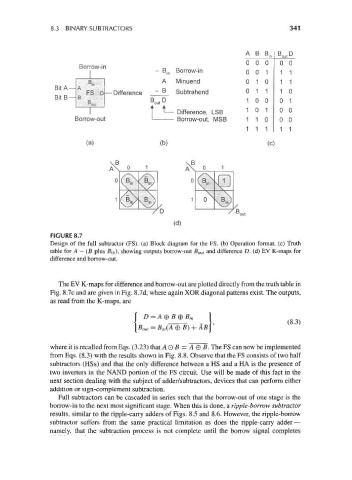
FIGURE 8.7
Design of the full subtracter (FS). (a) Block diagram for the FS. (b) Operation format, (c) Truth
table for A — (B plus Bj n), showing outputs borrow-out fi out and difference D. (d) EV K-maps for
difference and borrow-out.
The EV K-maps for difference and borrow-out are plotted directly from the truth table in
Fig. 8.7c and are given in Fig. 8.7d, where again XOR diagonal patterns exist. The outputs,
as read from the K-maps, are
D = A®*_®*, 1
where it is recalled from Eqs. (3.23) that A O B = A © B. The FS can now be implemented
from Eqs. (8.3) with the results shown in Fig. 8.8. Observe that the FS consists of two half
subtractors (HSs) and that the only difference between a HS and a HA is the presence of
two inverters in the NAND portion of the FS circuit. Use will be made of this fact in the
next section dealing with the subject of adder/subtractors, devices that can perform either
addition or sign-complement subtraction.
Full subtractors can be cascaded in series such that the borrow-out of one stage is the
borrow-in to the next most significant stage. When this is done, a ripple-borrow subtracter
results, similar to the ripple-carry adders of Figs. 8.5 and 8.6. However, the ripple-borrow
subtractor suffers from the same practical limitation as does the ripple-carry adder—
namely, that the subtraction process is not complete until the borrow signal completes