
Page 375 - Engineering Digital Design
P. 375
346 CHAPTER 8 / ARITHMETIC DEVICES AND ARITHMETIC LOGIC UNITS (ALUs)
adder. Introducing these equation into an expansion of Eqs. (8.6) gives
[ So = P 0 © Co 1
1st stage
1<-1 = -M)<-0 + CrOJ
2nd stage
s = ^2 e c 2
2
3rd stage \C 3 = P 2C 2 + G 2
==
P 2P\PQ^Q + P 2P\GQ + P 2Gi -f- G 2
: (8.8)
C D m /^
O^ —— i /| ^17 ^77
* — P C -\~ G
,1 . \^-«7_|_| — * n^n \^ ^-'w
nth stage •
D D D D /"* I D D D
— r nr n-\ r n-2 ' ' ' M)^0 " ^n^n-\ ^n-2
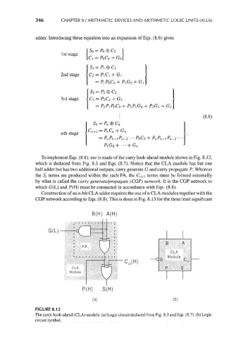
To implement Eqs. (8.8), use is made of the carry look-ahead module shown in Fig. 8.12,
which is deduced from Fig. 8.3 and Eqs. (8.7). Notice that the CLA module has but one
half adder but has two additional outputs, carry generate G and carry propagate P. Whereas
the Si terms are produced within the each FA, the C i+\ terms must be formed externally
by what is called the carry generate/propagate (CGP) network. It is the CGP network to
which G(L) and F(H) must be connected in accordance with Eqs. (8.8).
Construction of an n-bit CLA adder requires the use of n CLA modules together with the
CGP network according to Eqs. (8.8). This is done in Fig. 8.13 for the three least significant
B(H) A(H)
C ln(H)
P(H) S(H)
(a) (b)
FIGURE 8.12
The carry-look-ahead (CLA) module, (a) Logic circuit deduced from Fig. 8.3 and Eqs. (8.7). (b) Logic
circuit symbol.