
Page 371 - Engineering Digital Design
P. 371
342 CHAPTER 8 / ARITHMETIC DEVICES AND ARITHMETIC LOGIC UNITS (ALUs)
D(H)
FS
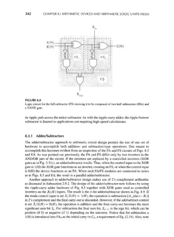
FIGURE 8.8
Logic circuit for the full subtractor (FS) showing it to be composed of two half subtracters (HSs) and
a NAND gate.
its ripple path across the entire subtractor. As with the ripple-carry adder, the ripple-borrow
subtractor is limited to applications not requiring high-speed calculations.
8.3.1 Adder/Subtractors
The adder/subtractor approach to arithmetic circuit design permits the use of one set of
hardware to accomplish both addition- and subtraction-type operations. One means to
accomplish this becomes evident from an inspection of the FA and FS circuits of Figs. 8.3
and 8.8. As was pointed out previously, the FA and FS differ only by two inverters in the
AND/OR part of the circuit. If the inverters are replaced by a controlled inverters (XOR
gates as in Fig. 3.3 Ic), an adder/subtractor results. Thus, when the control input to the XOR
gate is 1(H) the XOR gate functions as an inverter, creating an FS, or when the control input
is 0(H) the device functions as an FA. When such FA/FS modules are connected in series
as in Figs. 8.5 and 8.6, the result is a parallel adder/subtractor.
Another approach to adder/subtractor design makes use of 2's complement arithmetic
as discussed in Subsection 2.9.2. The design of the adder/subtractor now follows by using
the ripple-carry adder hardware of Fig. 8.5 together with XOR gates used as controlled
inverters on the #,(//) inputs. The result is the n-bit adder/subtractor shown in Fig. 8.9. If
the mode control input is set A/S(H} = !(//), the operation is subtraction [A, plus (—/?,-)]
in 2's complement and the final carry-out is discarded. However, if the add/subtract control
is set A/S(H) = 0(//), the operation is addition and the final carry-out becomes the most
significant sum bit S n. For subtraction the final sum bit, S n-\, is the sign bit, which can be
positive (if 0) or negative (if 1) depending on the outcome. Notice that for subtraction a
1(H) is introduced into FAo as the initial carry-in Co, a requirement of Eq. (2.14). Also, note