
Page 368 - Engineering Digital Design
P. 368
8.2 BINARY ADDERS 339
A n . r ... ,A 1 ,A 0
n-Bit
Ripple-Carry
Adder 0 = 0(H)
(a)
I ^2 ^1
^n-1
A • • • A A A
rt rt rt M A A A
n-1 2 1 0 n, .!. A 2 1 0
. D ••• Q D Q
n-1 2 1 0 +B,,, + B,
q Q ... c q q P Q LCS* l_p q . C* o
^n^n-l ^2 G 1 ^O w O 1 3 2 2 1 [^ . O n
(b) (c)
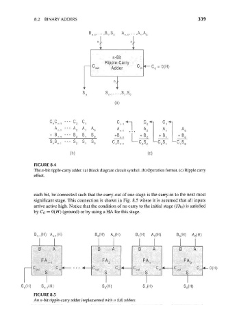
FIGURE 8.4
The n-bit ripple-carry adder, (a) Block diagram circuit symbol, (b) Operation format, (c) Ripple carry
effect.
each bit, be connected such that the carry-out of one stage is the carry-in to the next most
significant stage. This connection is shown in Fig. 8.5 where it is assumed that all inputs
arrive active high. Notice that the condition of no carry to the initial stage (M 0) is satisfied
by Q = 0(H) (ground) or by using a HA for this stage.
B n.,(H) A^H) B 2(H) A 2 (H) B^H) A,(H) B 0(H) A 0(H)
[3 / I3 /k B A
^
FA 2 FA, FA 0
0(H)
c c V ou, s
S n(H) S.^H) S 2(H) S^H) S 0(H)
FIGURE 8.5
An n-bit ripple-carry adder implemented with n full adders.