
Page 369 - Engineering Digital Design
P. 369
340 CHAPTER 8 / ARITHMETIC DEVICES AND ARITHMETIC LOGIC UNITS (ALUs)
R A R A
D
15-12 "15-12 D 11-8 "1
B A B A B A B A
4-Bit R-C 4-Bit R-C 4-Bit R-C 4-Bit R-C
Adder Adder Adder Adder
C C in •4 C out C in < C out g C in 4 C OUt C in -0(H)
out 0
o o o
4L 4 | 4 4
I I I I
1C S .,-.,, S.,., o ^7-4 ^3-0
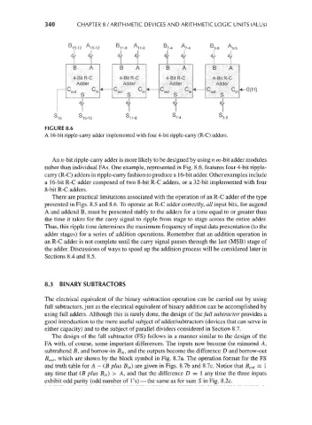
FIGURE 8.6
A 16-bit ripple-carry adder implemented with four 4-bit ripple-carry (R-C) adders.
An n-bit ripple-carry adder is more likely to be designed by using n m-bit adder modules
rather than individual FAs. One example, represented in Fig. 8.6, features four 4-bit ripple-
carry (R-C) adders in ripple-carry fashion to produce a 16-bit adder. Other examples include
a 16-bit R-C adder composed of two 8-bit R-C adders, or a 32-bit implemented with four
8-bit R-C adders.
There are practical limitations associated with the operation of an R-C adder of the type
presented in Figs. 8.5 and 8.6. To operate an R-C adder correctly, all input bits, for augend
A and addend B, must be presented stably to the adders for a time equal to or greater than
the time it takes for the carry signal to ripple from stage to stage across the entire adder.
Thus, this ripple time determines the maximum frequency of input data presentation (to the
adder stages) for a series of addition operations. Remember that an addition operation in
an R-C adder is not complete until the carry signal passes through the last (MSB) stage of
the adder. Discussions of ways to speed up the addition process will be considered later in
Sections 8.4 and 8.5.
8.3 BINARY SUBTRACTORS
The electrical equivalent of the binary subtraction operation can be carried out by using
full subtracters, just as the electrical equivalent of binary addition can be accomplished by
using full adders. Although this is rarely done, the design of the/w// subtractor provides a
good introduction to the more useful subject of adder/subtractors (devices that can serve in
either capacity) and to the subject of parallel dividers considered in Section 8.7.
The design of the full subtractor (FS) follows in a manner similar to the design of the
FA with, of course, some important differences. The inputs now become the minuend A,
subtrahend B, and borrow-in B in, and the outputs become the difference D and borrow-out
B out, which are shown by the block symbol in Fig. 8.7a. The operation format for the FS
and truth table for A — (B plus B in) are given in Figs. 8.7b and 8.7c. Notice that B out = 1
any time that (B plus B in) > A, and that the difference D = 1 any time the three inputs
exhibit odd parity (odd number of 1's) — the same as for sum S in Fig. 8.2c.